Installation guide, Calibration process: cwl models, Calibration process: cwe models – Veris Industries CW SERIES Install User Manual
Page 6: Cw series
Z204903-0M
PAGE 6
©2011 Veris Industries USA 800.354.8556 or +1.503.598.4564 / [email protected]
06114
Alta Labs, Enercept, Enspector, Hawkeye, Trustat, Veris, and the Veris ‘V’ logo are trademarks or registered trademarks of Veris Industries, L.L.C. in the USA and/or other countries.
TM
CW SERIES
INSTALLATION GUIDE
NITROGEN
GAS
Regulator
Valve
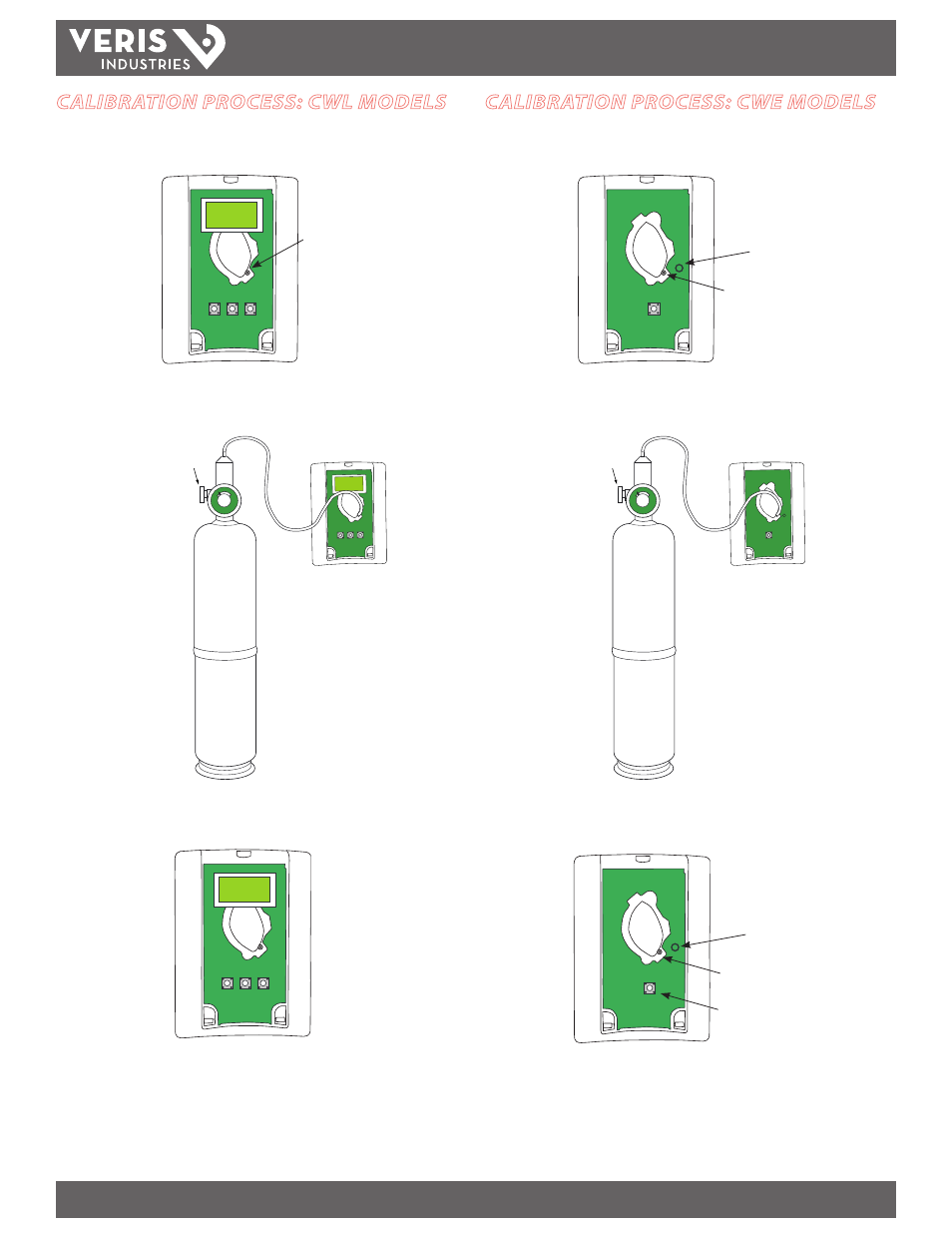
CALIBRATION PROCESS: CWL MODELS
1. Remove cover and connect gas cylinder hose to the plastic port located on sensing
module. Note: only connect one sensor to the calibration gas cylinder at a time.
800 PPM
70.0 ˚F
Connect hose
here
800 PPM
70.0 ˚F
NITROGEN
GAS
Regulator
Valve
CALIBRATION PROCESS: CWE MODELS
1. Remove cover and connect gas cylinder hose to the plastic port located on sensing
module. Note: only connect one sensor to the calibration gas cylinder at a time.
Connect
hose here
LED
indicator
Connect hose here
LED indicator
Calibration
button
2. Start flowing nitrogen gas (0 ppm CO
2
). Use a flow rate of 0.3 to 0.5 liter/minute.
3. Calibrate for 5 min. Unit will return to working display when finished.
4. When unit returns to working display, remove hose from calibration port and enter
Calibration mode as described on page 3.
2. Start flowing nitrogen gas (0 ppm CO
2
). Use a flow rate of 0.3 to 0.5 liter/minute.
3. Push and hold down calibration button until the LED illuminates.
4. Continue flowing gas through the sensor until the LED is off. Estimated calibration
time is 5 minutes. Remove hose from calibration port when complete.
For more complete calibration instructions using the
AA01 Calibration Kit, see the AA01 Installation Guide.