Installation guide, Dimensions, Installation – Veris Industries CW SERIES Install User Manual
Page 2: Operation, Cw series
Z204903-0M
PAGE 2
©2011 Veris Industries USA 800.354.8556 or +1.503.598.4564 / [email protected]
06114
Alta Labs, Enercept, Enspector, Hawkeye, Trustat, Veris, and the Veris ‘V’ logo are trademarks or registered trademarks of Veris Industries, L.L.C. in the USA and/or other countries.
TM
CW SERIES
INSTALLATION GUIDE
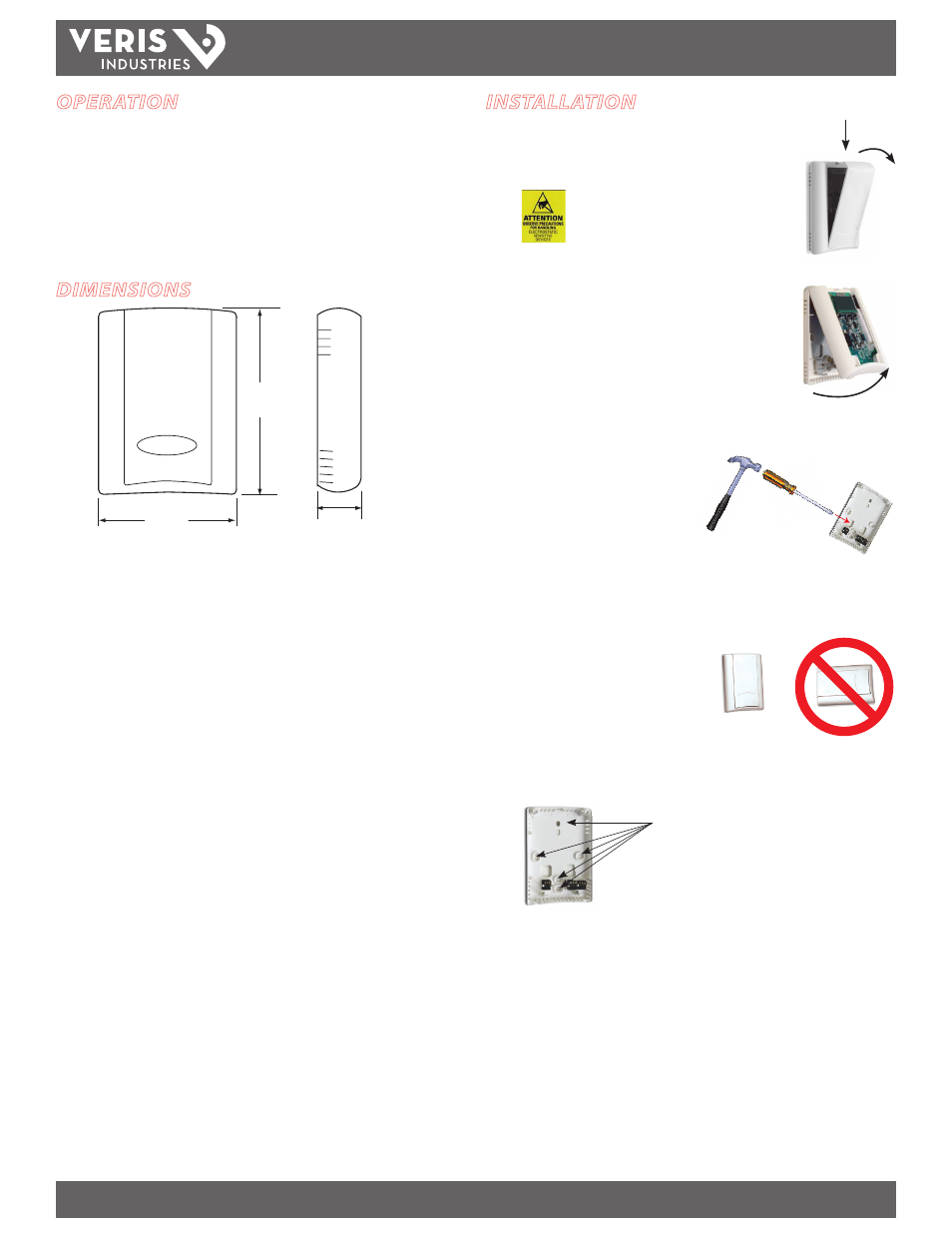
Five screwholes available; use a
minimum of two for secure mounting.
Observe handling precautions for static sensitive
devices to avoid damage to the circuitry which
would not be covered under the factory warranty.
DIMENSIONS
4.8"
(122 mm)
1.2"
(30 mm)
3.5"
(89 mm)
All optional
connector blocks
are shown here
for clarity.
All optional connector blocks are shown here for clarity.
INSTALLATION
1. Remove the cover by pressing the tab at the top of the sensor
while pulling outward from the top of the cover.
2. Remove the backplate by unfastening the sensor from the
bottom of the backplate and pivoting the sensor outward.
3. Punch out desired wire openings in the
backplate.
4. Position the sensor vertically on the wall,
4 1/2 feet above the floor. Locate away
from windows, vents, and other sources
of draft. If possible, do not mount on
an external wall, as this might cause
inaccurate temperature readings.
5. Mount the backplate onto the wall using the screws provided.
OPERATION
CW series wall mount CO
2
sensors measure the levels of CO
2
, RH (if equipped),
and temperature (if equipped) of air inside a duct. The CO
2
sensor operates within
accuracy specifications for an interval of 5 years and can be field calibrated. The
temperature element is warranted to meet accuracy specifications for a period of
5 years. RH equipped models feature a replaceable HS Series humidity element
that is warranted to meet accuracy specifications for a period of 1 year. To maintain
accuracy, all vents must remain clear and free of dust, debris, etc.