Installation guide, Cw series – Veris Industries CW SERIES Install User Manual
Page 3
Z204903-0M
PAGE 3
©2011 Veris Industries USA 800.354.8556 or +1.503.598.4564 / [email protected]
06114
Alta Labs, Enercept, Enspector, Hawkeye, Trustat, Veris, and the Veris ‘V’ logo are trademarks or registered trademarks of Veris Industries, L.L.C. in the USA and/or other countries.
TM
CW SERIES
INSTALLATION GUIDE
VOLT
AMP
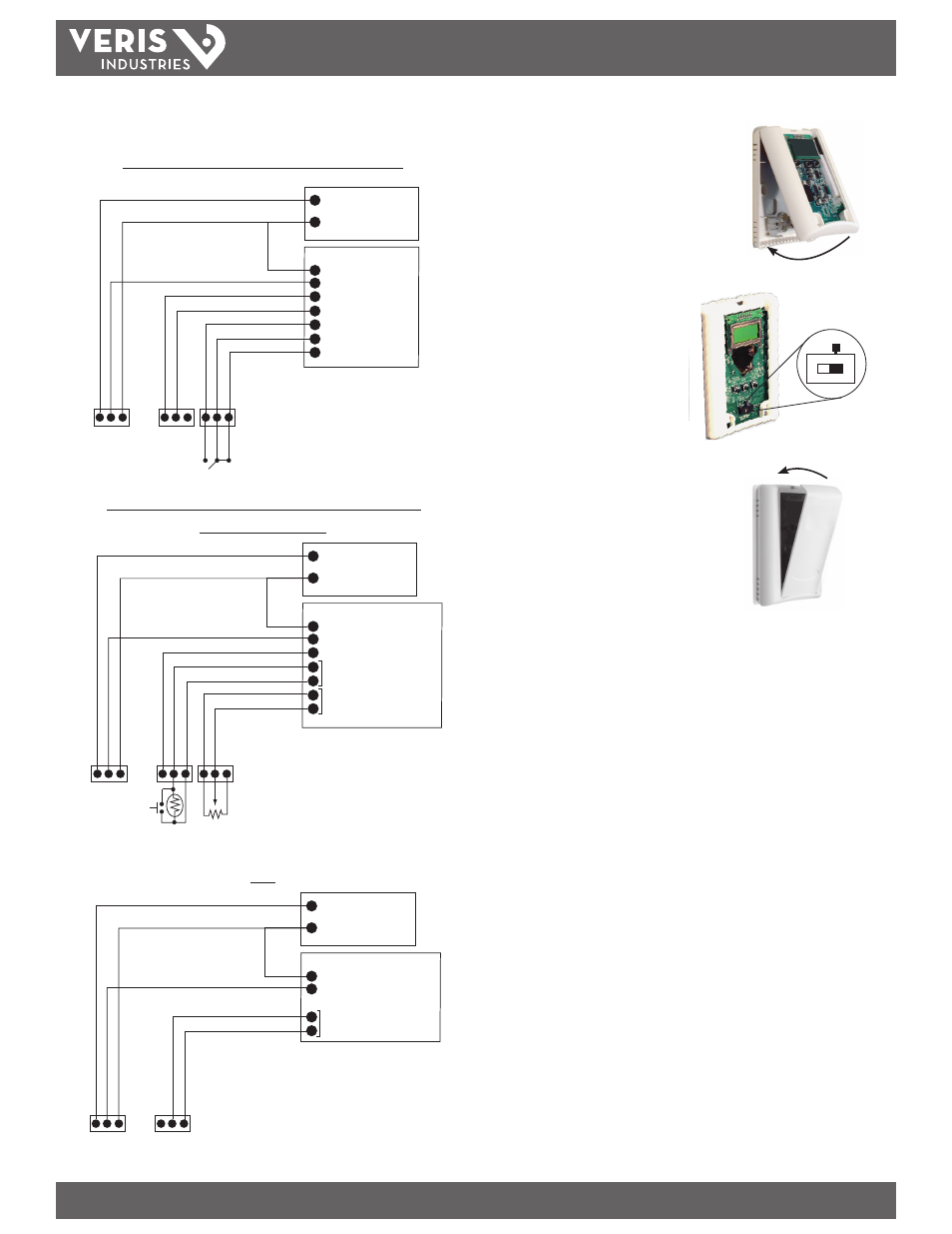
7. Install the sensor onto the backplate.
8. Use the switch to select voltage or
current output. For CWL model, see
Configuration section on page 4.
9. When installation is complete, install the
cover and snap into place.
POWER SUPPLY
20-30VDC, 24VAC
CONTROL SYSTEM
COMMON
CO2 INPUT
RH INPUT
TEMP INPUT
RELAY N.O.
COMMON
RELAY N.C.
PWR
COMMON
CO2 OUTPUT
RH OUTPUT
TEMP OUTPUT
REL
AY N.O
.
REL
AY N.C.
COMMON
+
-
-
POWER SUPPLY
20-30VDC, 24VAC
CONTROL SYSTEM
COMMON
CO2 INPUT
RH INPUT
THERMISTOR/OVERRIDE INPUT
SETPOINT SLIDER INPUT
PWR
COMMON
CO2 OUTPUT
RH OUTPUT
RTD/THERMIST
OR/O
VERRIDE
RTD/THERMIST
OR/O
VERRIDE
SLIDER RIGHT
SLIDER LEFT
SLIDER WIPER
+
-
-
CWL with RH and Temperature Transmitter Options
CWL with RH, Thermistor/RTD, Pushbutton Override, and
Setpoint Slider Options
Note: Relay contacts not available
in this configuration.
Note: Connector blocks and headers for
optional features are not included with
non-option models.
Note: Connector blocks and headers for
optional features are not included with
non-option models.
POWER SUPPLY
20-30VDC, 24VAC
CONTROL SYSTEM
COMMON
CO2 INPUT
THERMISTOR/OVERRIDE INPUT
PWR
COMMON
CO2 OUTPUT
RTD/THERMIST
OR/O
VERRIDE
RTD/THERMIST
OR/O
VERRIDE
+
-
-
CWE
6. Wire the backplate.