Veris Industries CW SERIES Install User Manual
Cw series, Notice, Wall mounted environmental co
Z204903-0M
PAGE 1
©2011 Veris Industries USA 800.354.8556 or +1.503.598.4564 / [email protected]
06114
Alta Labs, Enercept, Enspector, Hawkeye, Trustat, Veris, and the Veris ‘V’ logo are trademarks or registered trademarks of Veris Industries, L.L.C. in the USA and/or other countries.
TM
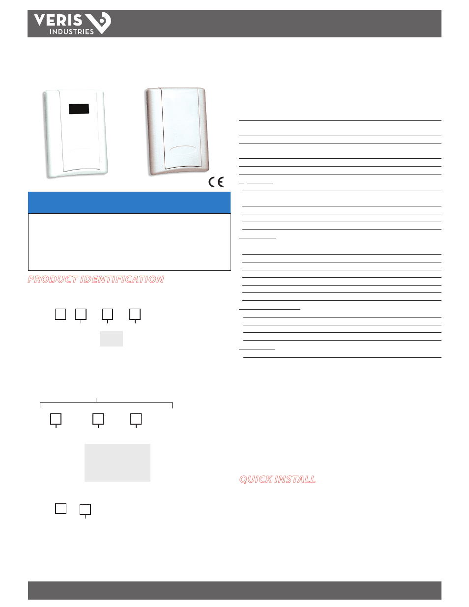
ENVIRONMENTAL SENSORS
INSTALLATION GUIDE
Wall Mounted Environmental CO
2
Sensors
Installer’s Specifications
Input Voltage
20 to 30VDC, 24VAC
Analog Output
CWL: 4-20mA (clipped and capped)/0-5VDC/0-10VDC (selectable)
CWE: 4-20mA (clipped and capped)/0-10VDC (selectable);
Sensor Current Draw
100mA max.
Operating Temperature Range
No humidity option: 0° to 50°C (32° to 122°F)
With
humidity option**: 10° to 35°C (50° to 95°F)
Operating Humidity Range
0-95% (noncondensing)
Housing Material
High impact ABS plastic
CO
2
Transmitter:
Sensor Type
Non-dispersive infrared (NDIR), diffusion sampling
Output Range
CWL: 0-2000 ppm or 0-5000 ppm, user selectable;
CWE: 0-2000 ppm
Accuracy
±30 ppm ±2% of measured value*
Repeatability
±20 ppm ±1% of measured value
Response Time
<60 seconds for 90% step change
RH Transmitter**:
HS Sensor
Digitally profiled thin-film capacitive (32-bit mathematics);
U.S.
Patent 5,844,138
Accuracy
±2% from 10 to 80% RH @ 25°C; Multi-point calibration NIST
Hysteresis
1.5% typical
Linearity
Included in Accuracy spec.
Stability
±1% @ 20°C (68°F) annually for two years
Output Range
0-100% RH
Temperature Coefficient
±0.1% RH/°C above or below 25°C (typical)
Temperature (Transmitter)**:
Sensor Type Thermistor
Accuracy
±0.5°C (±1°F) typical
Resolution
0.1°C (0.2°F)
Output Range
10° to 35°C (50° to 95°F)
Relay Contacts**:
1 Form C (on models without setpoint slider option)
1A@30VDC, resistive; 30W max.
Specified accuracy with 24VDC supplied power with rising humidity. RTD/Thermistors in wall
packages are not compensated for internal heating of product.
EMC Conformance: EN 61000-6-3:2001 Class B, EN 61000-6-1:2001, EN 61000-3-2:2000, EN
61000-3-3:2001
EMC Test Methods: CISPR 22:1997(Amended A9:2000, A2:2002), IEC 61000-4-2:2001, IEC 61000-4-
3:2002, IEC 61000-4-4:2004, IEC 61000-4-5:2001, IEC 61000-4-6:2004, IEC 61000-4-8:2001, IEC
61000-4-11:2004.
EMC Special Note: Connect this product to a DC distribution network or an AC/DC power adaptor
with proper SURGE PROTECTION (EN 61000-6-1:2001 specification requirements)
* Measured at NTP
** Not available on CWE
Note: Rough handling and transportation may cause a temporary reduction of CO
2
sensor
accuracy. With time, the ABC function will tune the readings back to the correct accuracy range.
The default tuning speed is limited to 30 ppm per week.
CW SerieS
CW SerieS
NOTICE
• This product is not intended for life or safety applications.
• Do not install this product in hazardous or classified locations.
• Read and understand the instructions before installing
this product.
• Turn off all power supplying equipment before working on it.
• The installer is responsible for conformance to all applicable codes.
PRODUCT IDENTIFICATION
RH Option Temp Sensor Type
A = Transmitter
B = 100R Platinum, RTD
C = 1k Platinum, RTD
D = 10k T2, Therm.
E = 2.2k, Therm.
F = 3k, Therm.
G = 10k CPC, Therm.
H = 10k T3, Therm.
T = Temp
X = No
(stop here)
H = RH 2%
X = No RH
CWL
CWE
WALL DELUXE MODELS:
WALL ECONOMY MODELS:
Sensor Type
B = 100R Platinum, RTD
C = 1k Platinum, RTD
D = 10k T2, Therm.
E = 2.2k, Therm.
F = 3k, Therm.
G = 10k CPC, Therm.
H = 10k T3, Therm.
J = 10k Dale, Therm.
S
S
CWL
CWE
Temp Cal Cert Option Setpoint Slider Value
1 = Push Button
Override *
2 = Set Point Slider
3 = Push Button
Override*+Set Point
Slider
–
A = 1k
F = 10k
G = 20k
K = 50k
M =100k
Options Available
X = No
1 = 1pt Temp Cal
2 = 2pt Temp Cal
* Note: the Pushbutton Override
feature is not available with
temperature transmitter models.
Only resistive temperature models
qualify for this feature.
K = 10k w/11k shunt, Therm.
M = 20k NTC, Therm.
N = 1800 ohm, Therm.
R = 10k US, Therm.
S = 10k 3A221, Therm.
T = 100k, Therm.
U = 20k “D”, Therm.
J = 10k Dale, Therm.
K = 10k w/11k shunt, Therm.
M = 20k NTC, Therm.
N = 1800 ohm, Therm.
R = 10k US, Therm.
S = 10k 3A221, Therm.
T = 100k, Therm.
U = 20k “D”, Therm.
QUICK INSTALL
1. Select a mounting location away from ventilation sources. The sensor should be
mounted on a vertical wall, about 4 1/2 feet above the floor.
2. Affix the backplate to the wall.
3. Wire the device. Refer to wiring diagrams on page 2.
4. Install Cover.