Rs-485 communications – Veris Industries E50H5A Install User Manual
Page 16
ZL0117-0D
Page 16 of 28
©2013 Veris Industries USA 800.354.8556 or +1.503.598.4564 / [email protected] 08131
Alta Labs, Enercept, Enspector, Hawkeye, Trustat, Aerospond, Veris, and the Veris ‘V’ logo are trademarks or registered trademarks of Veris Industries, L.L.C. in the USA and/or other countries.
Other companies’ trademarks are hereby acknowledged to belong to their respective owners.
Installation Guide
Power Monitoring
E50H2A, E50H5A
TM
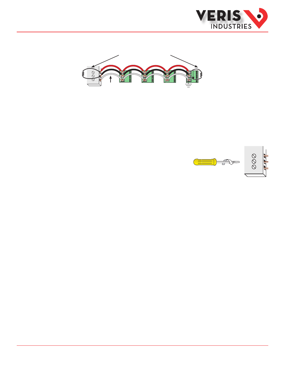
Daisy-chaining Devices to the Power Meter
The RS-485 slave port allows the power meter to be connected in a daisy chain with up to 63 2-wire devices.
–
+
S
120 Ω terminator on the first and last
device of the daisy chain
Shield wire
Notes
• The terminal’s voltage and current ratings are compliant with the requirements of the EIA RS-485 communications
standard.
• The RS-485 transceivers are ¼ unit load or less.
• RS-485+ has a 47 kΩ pull up to +5V, and RS-485- has a 47 kΩ pull down to Shield (RS-485 signal ground).
• Wire the RS-485 bus as a daisy chain from device to device, without any stubs. Use 120 Ω termination resistors at each
end of the bus (not included).
• Shield is not internally connected to Earth Ground.
• Connect Shield to Earth Ground somewhere on the RS-485 bus.
For all terminals:
• When tightening terminals, apply the correct torque: 0.37 to 0.44
ft·lb (0.5-0.6 N·m).
• Use 14-24 gauge (2.1-0.2 mm
2
) wire.
RS-485
Communications
Red
Black
Gray
0.37–0.44 ft•lb
(0.5–0.6 N•m)
Use 14-24 gauge wire