Pulse contact input, User interface (ui) menu abbreviations defined – Veris Industries E50H5A Install User Manual
Page 11
ZL0117-0D
Page 11 of 28
©2013 Veris Industries USA 800.354.8556 or +1.503.598.4564 / [email protected] 08131
Alta Labs, Enercept, Enspector, Hawkeye, Trustat, Aerospond, Veris, and the Veris ‘V’ logo are trademarks or registered trademarks of Veris Industries, L.L.C. in the USA and/or other countries.
Other companies’ trademarks are hereby acknowledged to belong to their respective owners.
Installation Guide
Power Monitoring
E50H2A, E50H5A
TM
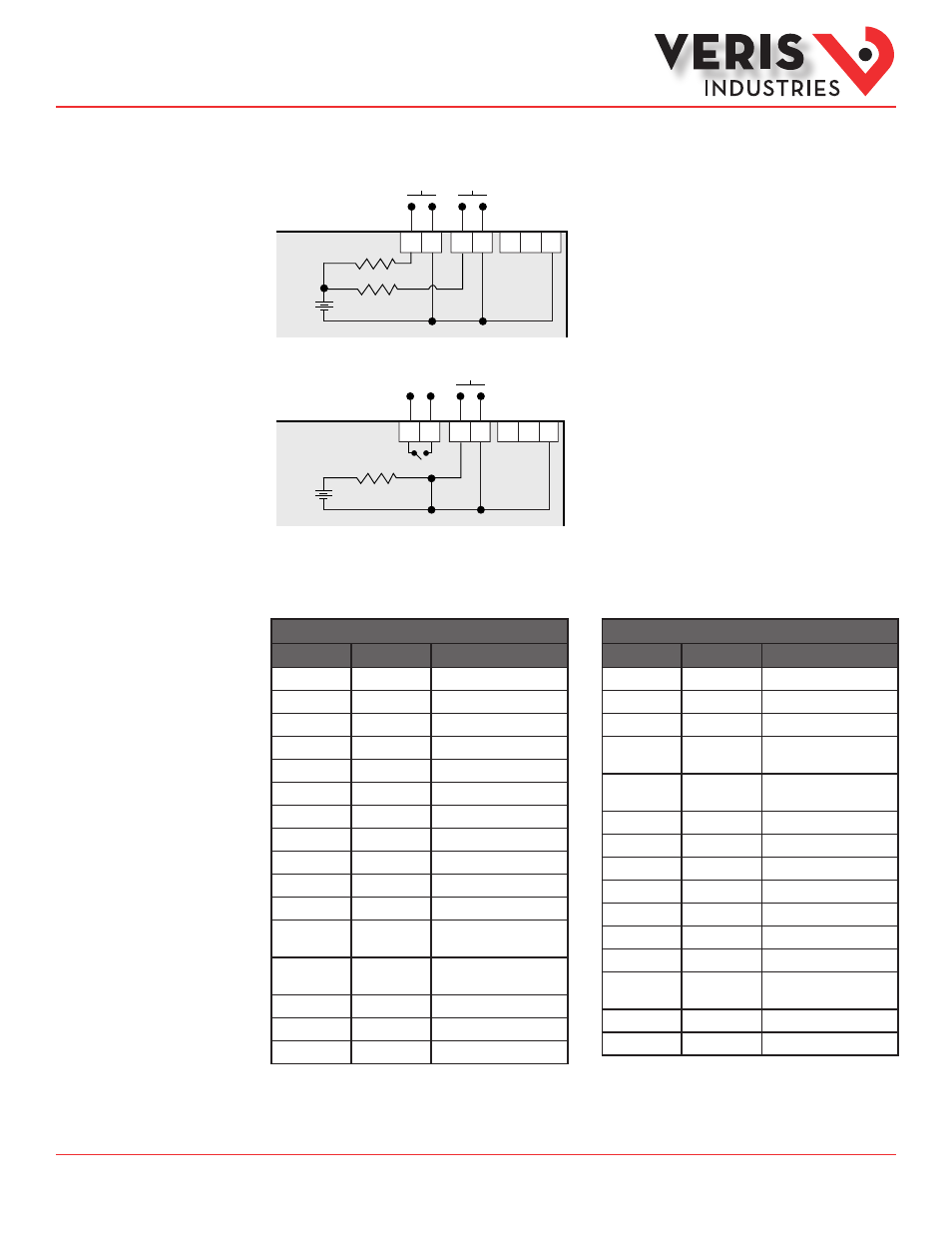
Pulse Contact Input
The E50H5A has two inputs with pulse accumulators for solid state or mechanical contacts in other sensors, such as water or gas
flow meters. These inputs are isolated from the measured circuits and referenced to the communication signal ground. Use with
contacts that do not require current to remove oxidation.
S
Comm
Output
+
~10 kΩ
Comm
Ground
4-10 VDC
nominal
Pulse Input
Contacts
Equivalent
Circuit
The E50H2A has one input with pulse accumulator as described above, and one phase loss alarm output terminal.
S
Comm
Output
+
~10 kΩ
Comm
Ground
4-10 VDC
nominal
Phase Loss
Alarm Output
Pulse Input
Equivalent
Circuit
Main Menu
IEC
IEEE
Description
D
D
Demand
MAX
M
Maximum Demand
P
W
Present Real Power
Q
VAR
Present Reactive Power
S
VA
Present Apparent Power
A
A
Amps
UAB, UBC, UAC
VAB, VBC, VAC
Voltage Line to Line
V
VLN
Voltage Line to Neutral
PF
PF
Power Factor
U
VLL
Voltage Line to Line
HZ
HZ
Frequency
KSh
KVAh
Accumulated Apparent
Energy
KQh
KVARh
Accumulated Reactive
Energy
KPh
KWh
Accumulated Real Energy
PLOSS
PLOSS
Phase Loss
LOWPF
LOWPF
Low Power Factor Error
Main Menu
IEC
IEEE
Description
F ERR
F ERR
Frequency Error
I OVR
I OVR
Over Current
V OVR
V OVR
Over Voltage
PULSE
PULSE
kWh Pulse Output Overrun
(configuration error)
_PHASE
_PHASE
Summary Data for 1, 2, or 3
active phases
ALERT
ALERT
Diagnostic Alert Status
INFO
INFO
Unit Information
MODEL
MODEL
Model Number
OS
OS
Operating System
RS
RS
Reset System
SN
SN
Serial Number
RESET
RESET
Reset Data
PASWD
PASWD
Enter Reset or Setup
Password
ENERG
ENERG
Reset Energy Accumulators
DEMND
DEMND
Reset Demand Maximums
User Interface (UI)
Menu Abbreviations
Defined
The user can set the display mode to either IEC or IEEE notation in the SETUP menu.