Wheel differential lock (cont’d) – Spicer Drive Axles Application Guidelines User Manual
Page 84
AXAG-0200 June 2009 84
Wheel Differential Lock (Cont’d)
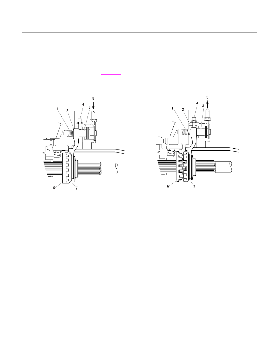
Differential Lock Engaged
Air pressure applied to the shift cylinder moves the
piston, push rod, shift fork and the sliding curvic
clutch engages the fixed curvic clutch.
The sliding clutch is splined to the
. The
fixed clutch is splined to the differential case hub.
Engaging the two clutches locks the wheel
differential thus preventing wheel differential action.
Differential Lock Disengaged
When air pressure at the shift cylinder is released, a
compression spring (mounted on the push rod) moves
the push rod, shift fork and sliding clutch as an
assembly. The sliding clutch moves out of engagement
with the fixed clutch. The wheel differential is
unlocked and operates normally.
Differential Lock Engaged
1 - Spring is compressed
2 - Shift fork
3 - Piston and rod
4 - Selector switch
5 - AIr pressure applied engages clutches
6 - Fixed clutch splined to differential case
7 - Sliding clutch splined to axle shaft and
engaged with fixed clutch
Differential Lock Disengaged
1 - Spring is decompressed
2 - Shift fork
3 - Piston and rod
4 - Selector switch
5 - AIr pressure released disengages clutches
6 - Fixed clutch splined to differential case
7 - Sliding clutch splined to axle shaft
Differential Lock Engagement Indicator
Differential lock engagement is detected by a switch
(electric) mounted on the differential carrier. An
actuator, mounted in the piston cover, operates the
switch.
When the shift fork moves to engage the differential
lock, the push rod actuator moves away from the
switch, allows the switch to close and send an
electrical signal to turn on a cab-mounted indicator
light (or an audible signal)
When the shift fork moves to disengage the
differential lock, the compression spring also moves
the push rod actuator to contact the switch. The
switch is opened and turns off the cab-mounted
indicator light (or the audible signal).