Spicer Single Drive Axles Service Manual: 34DS, 34RS, 38DS, 38RS, DS340, RS340, DS380, RS380, DS400, RS400, DS3 User Manual
Page 90
Differential Carrier Overhaul (Forward and Rear Axle)
87
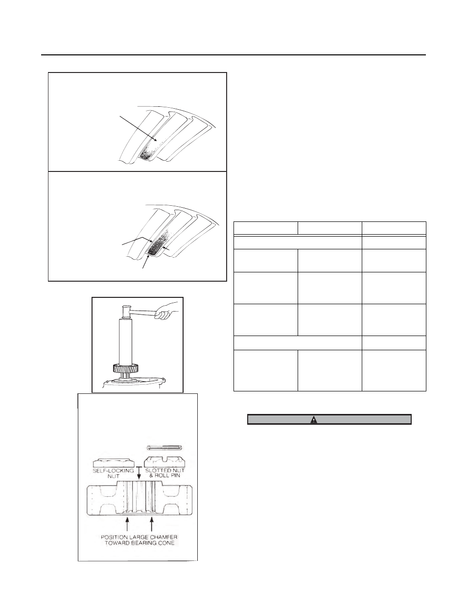
12. Check Ring Gear Tooth Contact. Paint ring gear teeth and
check tooth contact pattern. Correct tooth patterns are illus-
trated below. For checking and adjusting procedures, see
page 22.
13. With ring gear and pinion adjusted correctly, align adjusters
and locks, then tighten differential bearing cap screws to
correct torque (360-440 ft. lbs., 488-596 N.m). Install ad-
juster locks and cotter pins. Lock-wire differential bearing
cap screws.
14. Forward Axle Helical Gear. If dummy yoke was used, remove
nut and yoke. Install helical gear on pinion, positioned as
shown in the illustration. Install nut and tighten to correct
torque (see chart)
*Torque to 840 ft. lbs. (1139 N.m), then continue tighten-
ing nut to align slot with the nearest hole in pinion shank.
Install roll pin.
15. Installing Pinion Helical Gear.
Note: See Torque Chart for Pinion Nut Variations
Torque Chart
Size
Ft. lbs
N.m
Forward Axle Pinion Nut
(D340, 380(P),
400-P) 1 1/2-18
560-700
759-949
(D341, 381(P),
401-P, 402(P),
451-P) 1 5/8-18
780-960
1057-1301
(D341, 402(P)
403(P), 451-P)
M42 x 1.5
840-1020
1140-1383
Slotted Nut and Roll Pin
(D-341, 381(P),
401-P, 402(P),
451-P only ) 1 5/8-
18
840
1139
Pocket may be
extended.
Pattern along
the face width
could be longer.
Correct Pattern Used Gearing
Could vary in length.
Pattern should cover
1/2 tooth or more
(face width).
Pattern should be
evenly centered
between tooth
top land and root.
Pattern should be clear of tooth toe.
Correct Pattern New Gearing
IMPORTANT
Pinion Helical Gear
Mounting Position
NOTE:
See Torque Chart for
Pinion Nut Variations