Disassemble output shaft, Power divider overhaul, Procedure – Spicer Single Drive Axles Service Manual: 34DS, 34RS, 38DS, 38RS, DS340, RS340, DS380, RS380, DS400, RS400, DS3 User Manual
Page 54
Power Divider Overhaul
51
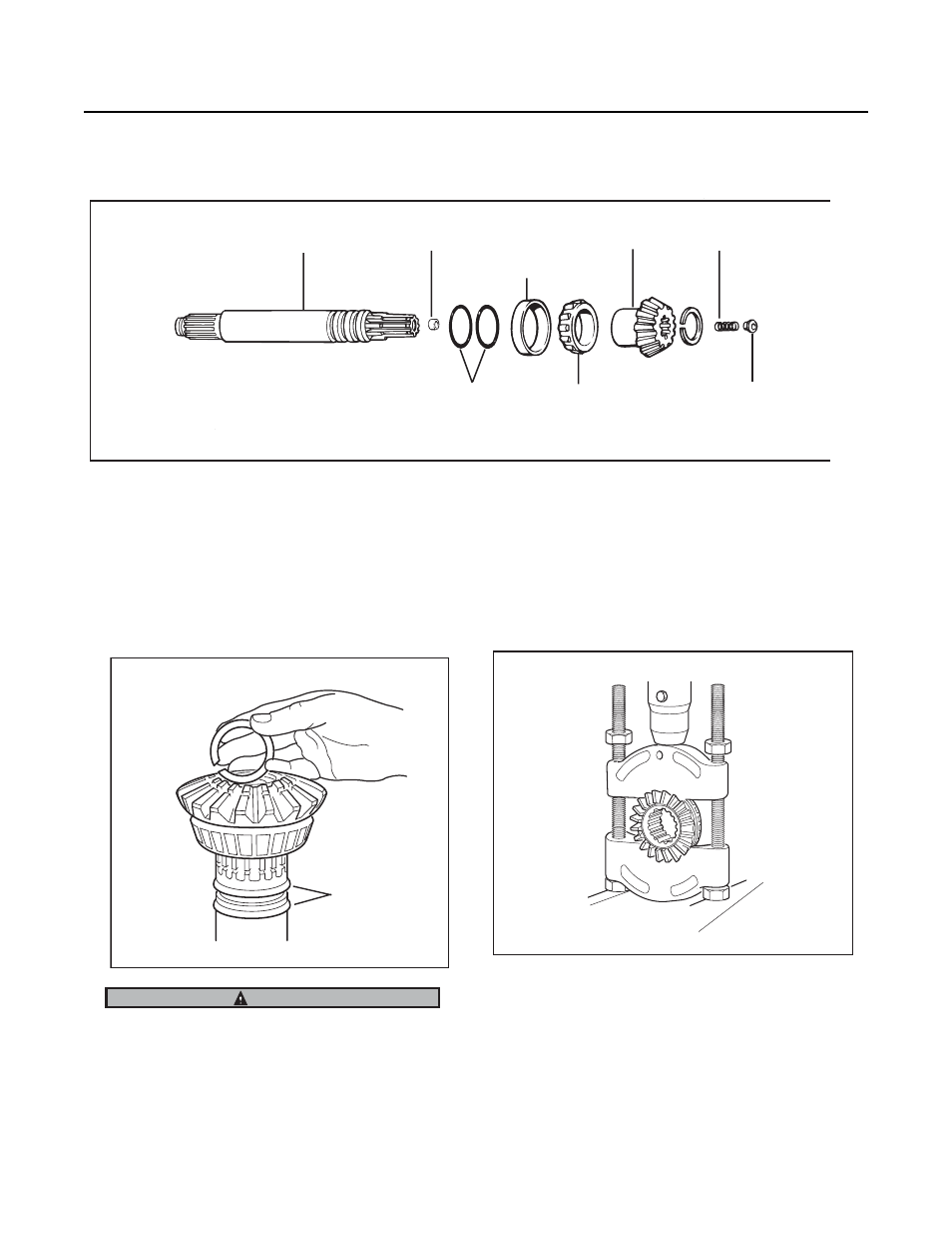
Disassemble Output Shaft
Procedure -
1.
Mount shaft assembly in vise using brass vise jaw protec-
tors. Remove outer snap ring, side gear and bearing cone
assembly. If replacement is necessary, remove inner snap
ring.
Snap ring is spring steel and may pop off, wear safety
glasses when removing.
2.
Remove output shaft "O" rings, If replacement is neces-
sary, remove bushing mounted in end of output shaft.
(NOTE 1) .
3.
Remove bearing cone from side gear using press and
split-type puller.
Note: For instructions covering output shaft rear bearing
parts, see page 26.
Note: Starting in June 1993, production axles were made
with bushing less output shaft 128736. Do not at-
tempt to install bushings in shafts with P/N's
128736 or 129194* stamped into them. Ref. bulle-
tin AXIB-93-06 *(output shaft w/metric threads
used in axles after 1-3-95).
*Bushing removed from current production axles in Sept. 1994. Output shafts with P/N 129016 do not use bushings.
Output shaft
*Bushing
O-rings
Bearing cup
(mounted in
carrier)
Bearing cone
Side gear
Spring
Button
Output Shaft Assembly
.
NOTE: Late Model Axles may be equipped
with a spring and thrust button mounted
between the input shaft and output shaft.
O-rings
WARNING
Removing Bearing Cone from Output Shaft Side Gear