Power divider replacement – Spicer Single Drive Axles Service Manual: 34DS, 34RS, 38DS, 38RS, DS340, RS340, DS380, RS380, DS400, RS400, DS3 User Manual
Page 44
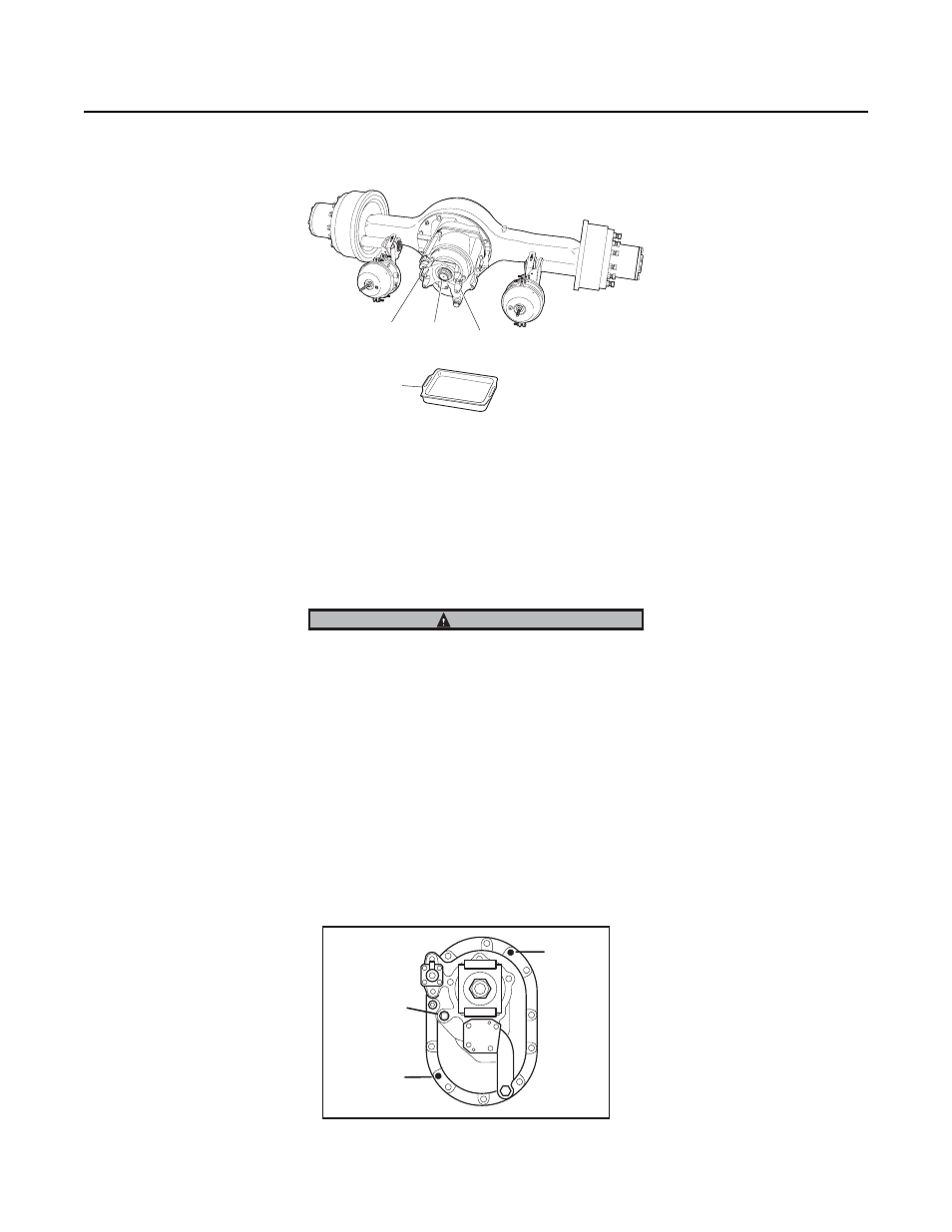
Power Divider Replacement
41
Procedure - Remove Power Divider from Differential Carrier
1.
Disconnect main driveline.
2.
Loosen, but do not remove input yoke nut.
3.
Disconnect lockout air line.
4.
Position drain pan under power divider cover.
5.
To remove power divider assembly, remove cover cap screws and lock washers. Support power divider (see instructions
above). Then, tap back-face of input yoke to dislodge cover from differential carrier. If cover does not dislodge easily, strike
the sides of the cover near the dowel pin locations (see illustration). Drain lube.
During removal of power divider, the lnter-axle differential may fall from carrier. Exert caution to prevent damage or in-
jury.
6.
Pull power divider assembly forward until it is completely free of carrier, then remove the assembly.
7.
With power divider removed, the inter-axle differential can be lifted off output shaft side gear .
Note: Late model axles may be equipped with a compression spring and thrust button mounted between the input shaft and
output shaft .
8.
Output Shaft. If necessary, remove output shaft as follows: Disconnect inter-axle driveline. Remove nut, flat washer and out-
put shaft yoke. Pull output shaft assembly out of carrier.
9.
Axle Housing Cover and Output Shaft Bearing Parts. If necessary, remove these parts following instructions.
3.
Lockout
air line
2.
Input
yoke nut
1.
Main
driveline
4.
Drain
pan
CAUTION
Dowel Pin
Dowel Pin
Socket Head
Capscrew