Assemble power divider cover, Power divider overhaul, Ser vice procedure – Spicer Single Drive Axles Service Manual: 34DS, 34RS, 38DS, 38RS, DS340, RS340, DS380, RS380, DS400, RS400, DS3 User Manual
Page 57
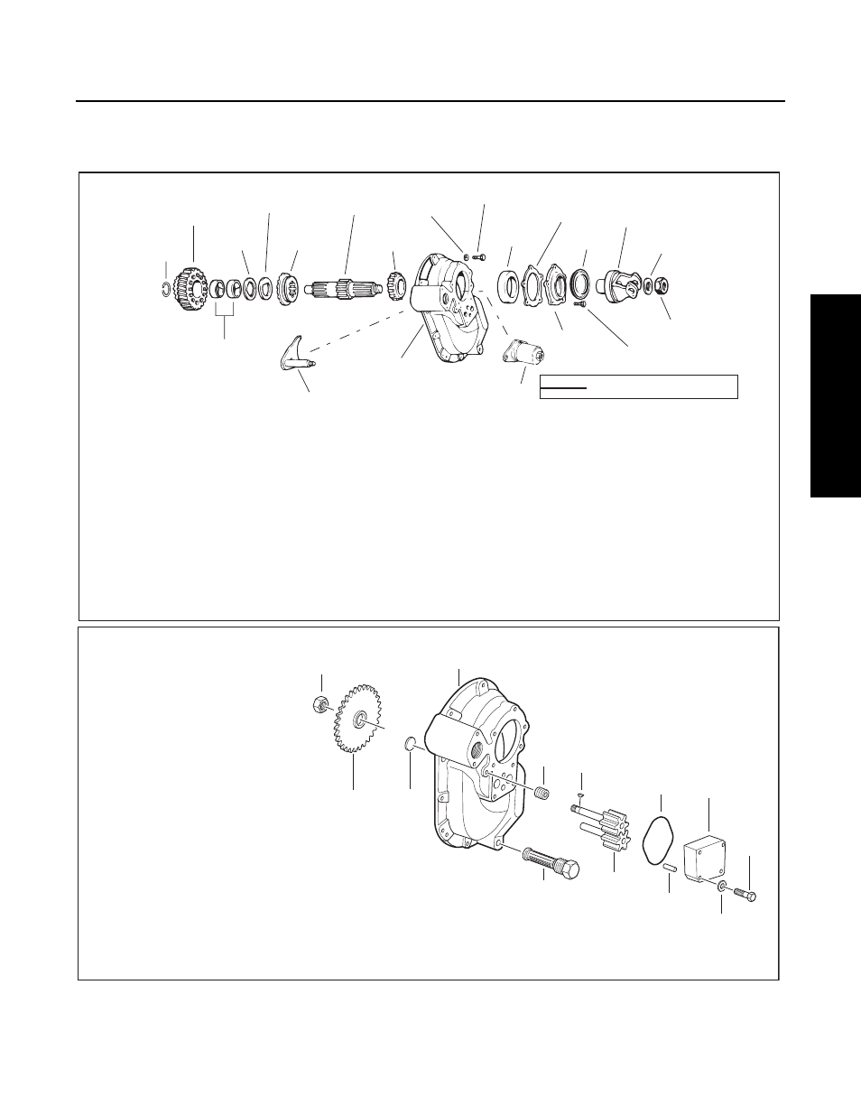
Power Divider Overhaul
54
Ser
vice Procedure
Assemble Power Divider Cover
Note: Axles with Lube Pump. Assemble and install lube pump and magnetic screen. See steps 1 to 4.
1
2
21
3
4
5
6
7
19
8
9
16
13
10
11
17
12
14
15
18
20
1
Snap ring
2
Helical side gear
3
Thrust washer
4
D washer
5
Lockout sliding clutch
6
Input shaft
7
Bearing cone
8
Lockwasher
9
Capscrew
10
Bearing cup
11
Shim
12
Oil seal
13
Yoke
14
Flat washer
15
Nut
16
Capscrew
17
Bearing cover
18
Lockout unit (See lockout service
instructions for design variations
19
Power divider cover
20
Shift fork and push rod
21
Bushings
Power Divider
(without Lube
Cover and Input Shaft
Pump)
LOCKOUT FOR DESIGN VARIATIONS REFER
TO LOCKOUT SERVICE INSTRUCTIONS
1
2
3
4
5
6
7
8
9
10
13
12
11
*NOTE: The drive shaft on early pump models is equipped with a woodruff key. On late pump models, the key is eliminated. The drive shaft end has two
machined flats and the drive gear mounting hole is shaped to accommodate these flats.
1
Lock nut
2
Power divider cover
3
Pipe plug
4
Woodruff key*
5
O-ring
6
Pump cover
7
Capscrew
8
Lockwasher
9
Dowel pin
10
Pump gears
11
Magnetic strainer
12
Expansion plug
13
Pump drive gear
Power Divider Cover with Lube Pump.