Making external connections to the relays (cont.) – Ohaus CKW WASHDOWN CHECKWEIGHING SCALES_INDICATOR Relay Option Kit Manual multi User Manual
Page 6
CKW Relay Option Kit
EN-5
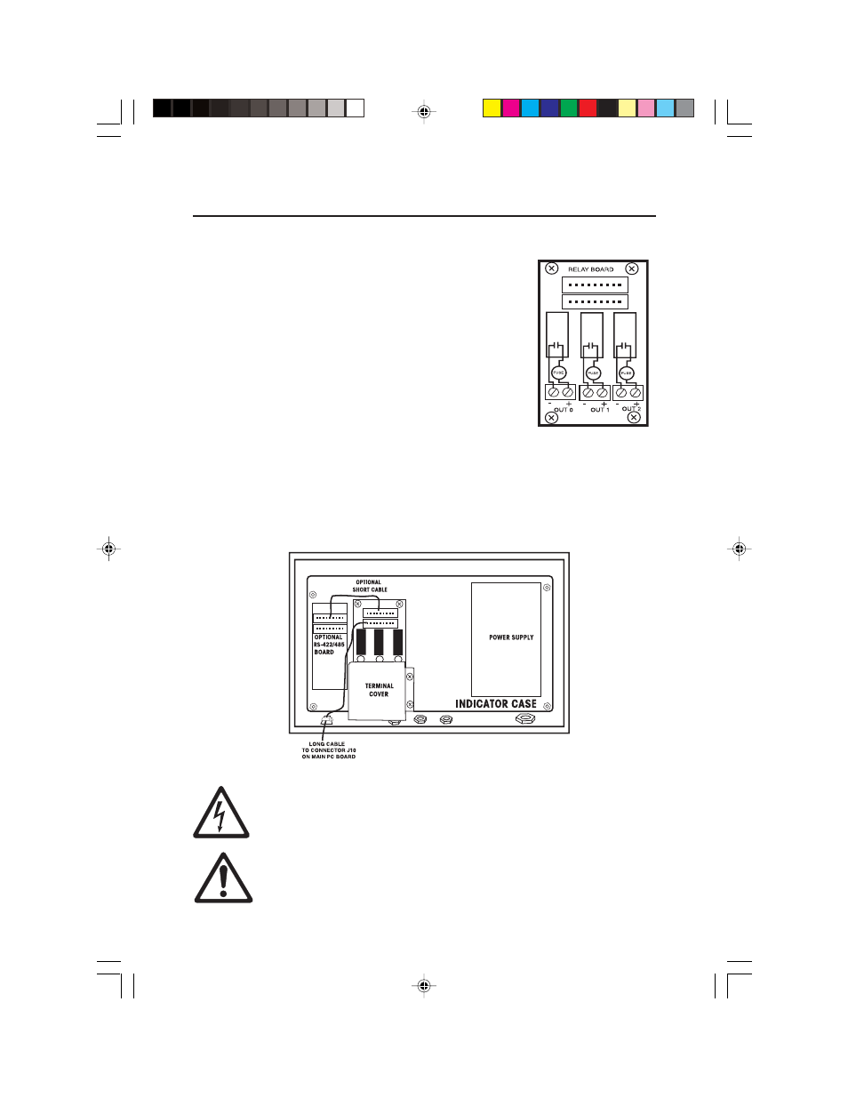
Figure 3. Relay Output
Board Contact Diagram.
• Each relay output has two terminals, connect each
wire pair to be switched to each set of terminals. See
Figure 3, for a relay contact diagram.
• For DC relay boards, make sure the polarity is correct.
• The DC Relay PCB can only be used with DC circuits.
• The AC Relay PCB can only be used with AC circuits.
• After making the proper connections, tighten the
external nut of the liquid-tight connector securely
around the cable.
• Install the Relay Terminal Cover as shown in
Figure 4 using the two screws supplied.
• The relay connections provide a switch closure only, AC or DC power must be
supplied externally.
• For reference, Appendix A shows typical examples of wiring to the relays.
Making External Connections to the Relays (Cont.)
Figure 4. Relay Output Board With Cover in Place.
CAUTION: Do not operate the Relay Option without the terminal cover
in place.
IMPORTANT: Review the I/O menu before using the relay option board
to control external devices.
2 TEXT-EN.pmd
3/21/2005, 2:16 PM
5
- MB45 MOISTURE ANALYZER Manual (70 pages)
- PRIMER BALANCE Manual (16 pages)
- DEFENDER 5000 BENCH SCALES Cable Adapter Kit Manual multi (2 pages)
- CARAT PLUS PRECISION JEWELRY BALANCES 2nd RS232 Serial Interface Kit Manual multi (24 pages)
- DEFENDER 5000 Semi-Washdown Scales Data Sheet (4 pages)
- SCOUT PRO PORTABLE BALANCES Data Sheet (4 pages)
- JR Series Electronic Balances (32 pages)
- EB COMPACT SCALES Data Sheet (2 pages)
- E1M110 Explorer Balances (47 pages)
- CKW WASHDOWN CHECKWEIGHING SCALES_INDICATOR Manual en (68 pages)
- RANGER COUNT 3000 COMPACT COUNTING SCALES Data Sheet (4 pages)
- RANGER ADVANCED COMPACT COUNTING SCALES Manual en (72 pages)
- Valor 2000 COMPACT FOOD SCALES Data Sheet (4 pages)
- DEFENDER D500M MECHANICAL BENCH SCALE Data Sheet (2 pages)
- CKW BASE Manual multi (40 pages)
- Valor 3000 COMPACT FOOD SCALES Manual multi (104 pages)
- Valor 1000 COMPACT FOOD SCALES Data Sheet (2 pages)
- PAJ GOLD PLUS PRECISION JEWELRY BALANCES Data Sheet (4 pages)
- Voyager Balances (329 pages)
- SD COMPACT BENCH SCALES Data Sheet (2 pages)
- AS Series Electronic Balances (89 pages)
- CL PORTABLE BALANCES Manual multi (44 pages)
- CL PORTABLE BALANCES Data Sheet (2 pages)
- HH 120D HAND HELD SCALES Manual multi (40 pages)
- CD-11 Indicator Manual multi (120 pages)
- CARAT PLUS PRECISION JEWELRY BALANCES Manual en (56 pages)
- SCOUT PRO PORTABLE BALANCES Installation it (2 pages)
- DEFENDER 7000 BENCH SCALES Base Manual (2 pages)
- GT4100DG Electronic Balances (52 pages)
- FD Series STAINLESS STEEL COMPACT SCALES Manual multi (88 pages)
- PL150 Scale Bases (10 pages)
- DEFENDER 3000 BENCH SCALES Base Manual en (8 pages)
- DEFENDER 3000 Xtreme Data Sheet (2 pages)
- HJ2001 HARVARD JUNIOR MECHANICAL BALANCE Data Sheet (2 pages)
- VN Series Floor Scale Data Sheet (4 pages)
- DS Series Electronic Digital Bench Scales (38 pages)
- YA GOLD HAND HELD JEWELRY SCALES Data Sheet (2 pages)
- DEFENDER 7000XW Xtreme Square Washdown Scales Data Sheet (4 pages)
- DEFENDER 7000 Square Semi-Washdown Scales Data Sheet (4 pages)
- PS POCKET JEWELRY SCALES Data Sheet (2 pages)
- RANGER COMPACT HIGH RESOLUTION SCALES Data Sheet (2 pages)
- CARAT & GOLD LIGHT PORTABLE JEWELRY BALANCES Manual multi (88 pages)
- 311 CENT-O-GRAM BALANCE Manual (8 pages)
- DEFENDER 5000 Rectangular Scales Data Sheet (4 pages)
- MB301 Electronic Balances (29 pages)