Making external connections to the relays – Ohaus CKW WASHDOWN CHECKWEIGHING SCALES_INDICATOR Relay Option Kit Manual multi User Manual
Page 5
EN-4
CKW Relay Option Kit
Making External Connections to the Relays
IMPORTANT: When connecting any AC line supplied device to the Relay
Option PCB, insure that each external device utilizes a properly
grounded AC connection.
• For connections to nominal 120 VAC or 220-240 VAC systems, use only
insulated wire sets rated to the local electrical code requirements.
• The wire set used for connection to the relay option PCB should be part of a
multi-conductor cable with a smooth, round outer insulating jacket.
• Do not run more than one cable through the watertight fitting.
• Do not run other low voltage wires within the same cable set that connects
to the Relay connections.
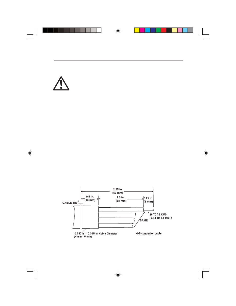
• The overall cable diameter must be between 0.157 in. to 0.315 in.,
(4 mm to 8 mm).
• The terminal connections require wire sizes in the range of 26 to 16 AWG,
(0.14 mm
2
to 1.5 mm
2
). Wire ends are stripped to 0.25 in. (6 mm). Follow
Figure 2 to strip cable and wire ends to the correct lengths.
• The cable from the Relay terminals must be routed directly to the watertight
fitting at the left side of the Indicator housing. This is the closest fitting just
below the Relay PCB. See Figure 1.
Figure 2. Cable Preparation.
*NOTE: Install the Cable Tie after inserting the cable through the liquid-tight fitting.
2 TEXT-EN.pmd
3/21/2005, 2:16 PM
4