Wiring to the serial interface board, Setup jumpers – Ohaus CKW WASHDOWN CHECKWEIGHING SCALES_INDICATOR CKW RS485_422 Serial Interface Option Kit Manual multi User Manual
Page 5
EN-4
CKW Serial Interface Option Kit
Wiring to the Serial Interface Board
The wire set used for connection to the Serial Interface option PCB should be part
of a multi-conductor cable with a round outer insulating jacket. The overall cable
diameter will need to be between 0.157 in. to 0.315 in., (4 mm to 8 mm).
• The terminal connections require wire sizes in the range of 26 to 16 AWG,
(0.14 mm
2
to 1.5 mm
2
). Wire ends are stripped to 0.25 in. (6 mm).
• The cable set from the RS485/422 may be routed directly to the liquid-tight
fitting at the left side of the Indicator housing. If this fitting is not available,
use the fitting to the far right instead.
• Connect the cable wires as indicated by the signal names on the PCB.
• Install and securely tighten a cable tie on to the cable just above the liquid-
tight fitting.
• After making the proper connections, tighten the liquid-tight connector
securely around the cable outside of the case.
• Reinstall the front cover and make sure the liquid-tight connector is tight.
• Refer to the CKW-55 Indicator Instruction manual for operational details.
CAUTION: Do not run high voltage wiring within the same cable set that connects
to the serial communication circuits.
To maintain a liquid-tight enclosure, do not run more than one cable
through each liquid-tight fitting.
SETUP
Jumpers
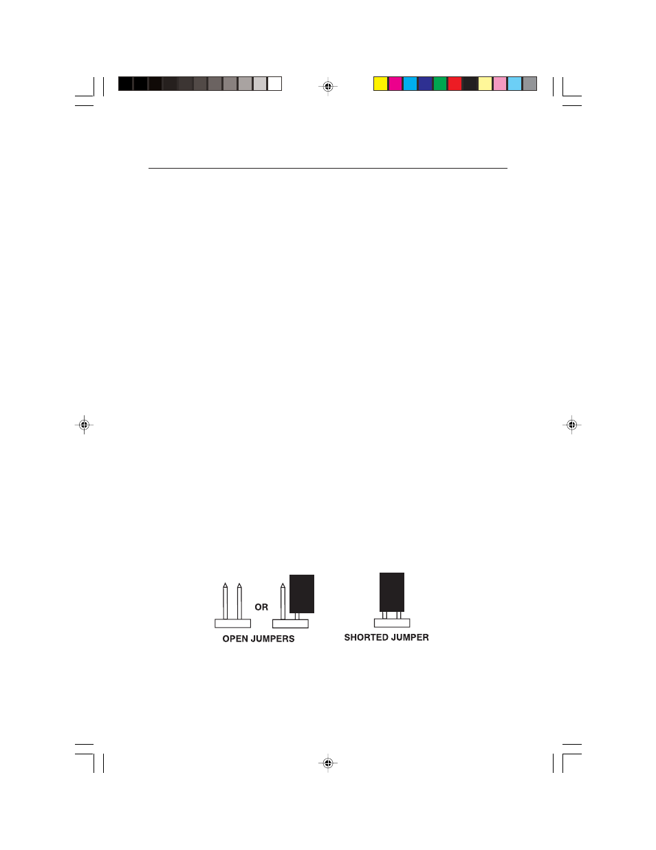
Two shorting jumpers are provided on the RS485/422 PCB. Jumper W1 is used
to select the 2 or 4-wire operating mode. Jumper W2 provides for an optional
termination resistance. Refer to Figure A.1 in Appendix A for W1 and W2 jumper
locations. Figure 2 below shows the proper positioning of the jumper
components.
Figure 2. Open and Shorted Jumpers.
2 TEXT-EN.pmd
1/28/2005, 11:10 AM
4