3 jumper settings – Acnodes FES 5313 User Manual
Page 21
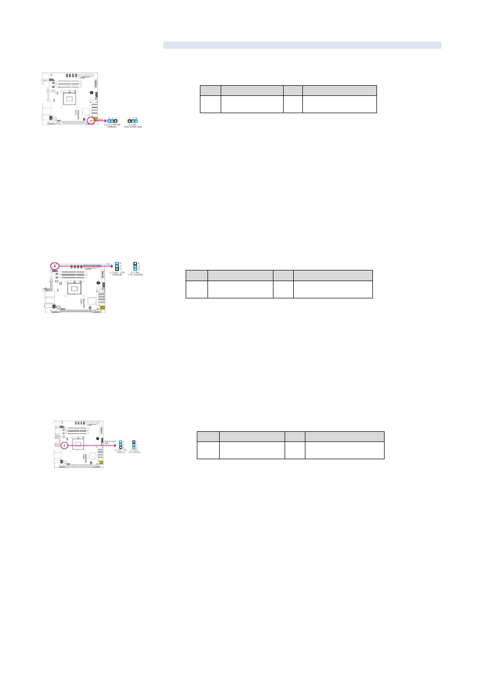
2-3 Jumper Settings
Clear CMOS Data
Pin
Definition
Pin
Definition
1-2
Normal(default)
2-3
Clear CMOS Data
If you encounter the following,
a) CMOS data becomes corrupted.
b) You forgot the supervisor or user password.
You can reconfigure the system with the default values stored in the ROM BIOS. To
load the default values stored in the ROM BIOS, please follow the steps below.
1. Power-off the system and unplug the power cord.
2. Set JP10 pins 2 and 3 to On. Wait for a few seconds and set JP10 back to its default setting, pins 1 and 2 On.
3. Now plug the power cord and power-on the system.
PS/2 Power Select
Pin
Definition
Pin
Definition
1-2
On: +5V(default)
2-3
+5V_standby
JP2 is used to select the power of the PS/2 keyboard and PS/2 mouse ports. Selecting +5V_standby will allow you to use the PS/2 keyboard
or PS/2 mouse to wake up the system.
Important:
The +5VSB power source of your power supply must support 720mA.
USB Power Select
Pin
Definition
Pin
Definition
1-2
On: +5V(default)
2-3
+5V_standby
This jumper is used to select the power of the USB ports. Selecting +5V_standby will allow you to use a USB device to wake up the system.
Important:
If you are using the Wake-On-USB Keyboard/Mouse function for 2 USB ports, the +5V_standby power source of your power supply must
support 1.5A. For 3 or more USB ports, the +5V_standby power source of your power supply must support 2A.
Jumper Setting