Jet Tools C30 User Manual
Page 82
5.
NORME DI MESSA A PUNTO • SET-UP PROCEDURES
ENGLISH
ITALIANO
– 84 –
040_025_0.tif
5
040_026_2.tif
6
F
A
B
D
C
G
E
F
7
F
040_083_0.tif
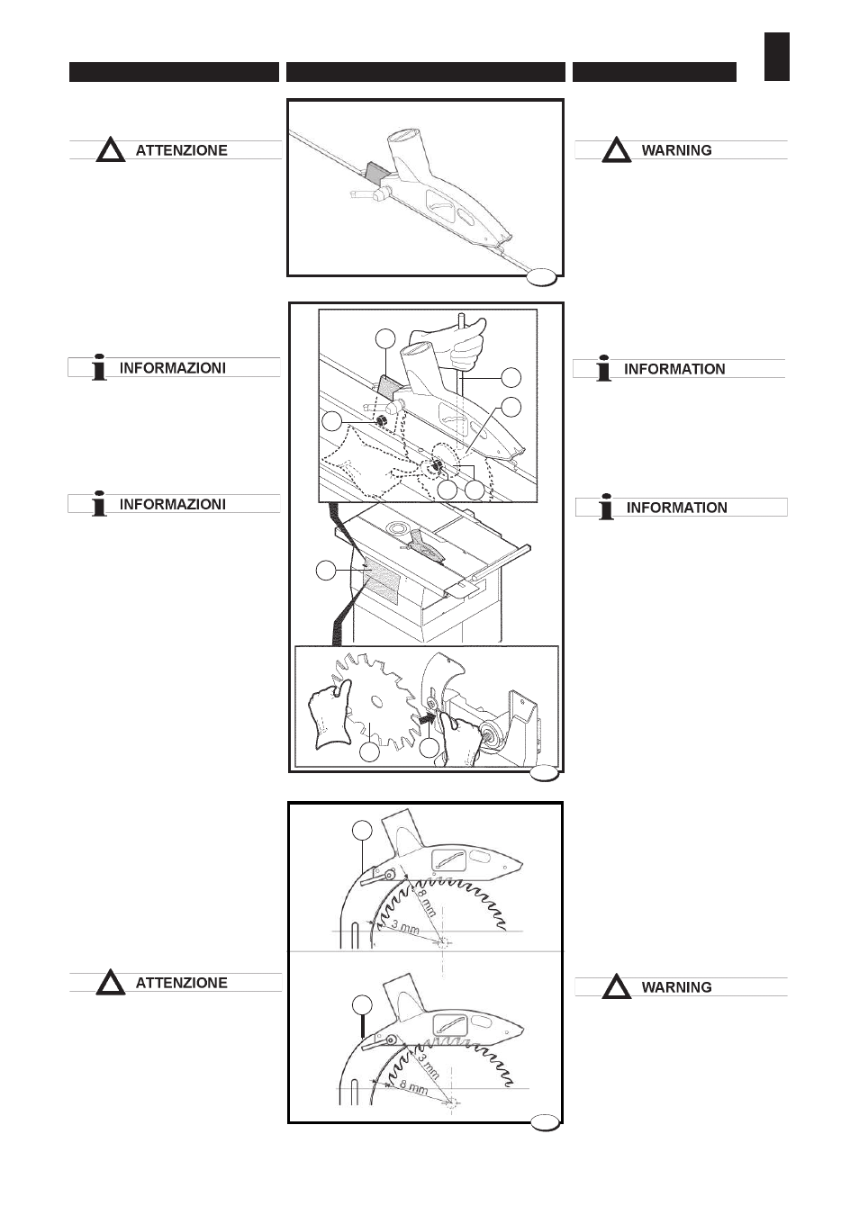
5.1.3 Sega circolare -
Montaggio
Maneggiare gli utensili
utilizzando i guanti di protezione.
– Disinserire la tensione di alimen-
tazione.
– Posizionare il gruppo sega a 90°
e abbassarlo al massimo.
Predisporre la macchina seguen-
do le indicazioni:
L'operazione deve essere
effettuata attraverso lo sportello
di accesso A.
– Inserire il perno
B nel foro della
puleggia albero sega.
Il dado di bloccaggio C della lama
sega è sinistrorso; per svitarlo
occorre ruotarlo in senso orario.
– Allentare il dado di bloccaggio
C con chiave esagonale da 24
mm, ed estrarre la fl angia
D.
– Montare in sequenza la sega
E,
la fl angia
D e il dado C (per evi-
tare eventuali vibrazioni, prima
di montare la lama sega pulire
accuratamente le fl ange).
– Per agevolare l'inserimento del-
la sega
E, è necessario allargare
leggermente il convogliatrucioli
e far passare la sega stessa
attraverso la fessura creatasi in
corrispondenza della freccia
H.
– Serrare il dado con la chiave da
24 mm utilizzando il perno
B.
– Regolare la posizione in altezza
del coltello divisore
F allentando
il dado
G.
Regolare la posizione del coltello
divisore in modo che la sua
distanza dalla lama sega sia
compresa fra 3 e 8 mm
(vedi esempio fi g. 7).
Il coltello divisore è nella giusta
posizione quando la protezione
sega copre una parte del
tagliente della lama sega.
5.1.3 Circular saw -
Assembly
Handle the tools with protective
gloves.
– Disconnect input power.
– Position the saw unit at 90° and
lower it as far as it will go.
Prepare the machine following
these instructions:
This operation must be performed
using access door A.
– Fit pin
B into the saw shaft pulley
hole.
The locking nut C of the saw blade
is counter-clockwise; to unscrew it
turn it clockwise.
– Loosen the lock nut
C using a
24 mm hex wrench and remove
fl ange
D.
– In sequence mount the saw
E, the
fl ange
D and the nut C (to prevent
any vibration, thoroughly clean
the fl anges before mounting the
saw blade).
– To make is easier to insert the
saw
E, you must widen the chip
conveyor slightly and allow the
saw to pass through the space
created in correspondence to
arrow
H.
– Tighten the nut using the
24 mm wrench and the pin
B.
– Adjust dividing knife
F height by
unloosing nut
G.
Adjust the position of the riving
knife so that its distance from the
saw blade is between 3 and 8 mm
(see example in fi g.7).
The dividing knife is in the right
position when the saw guard
covers a part of the cutting edge of
the saw blade.
H
E