Hardware installation & initial setup, Front panel leds of the p642r, Rear panel and connections of the prestige 642r – ZyXEL Communications Prestige 642R Series User Manual
Page 32: Chapter 2 hardware installation & initial setup, 1 front panel leds of the p642r, 2 rear panel and connections of the prestige 642r
Prestige 642R Series ADSL Router
Hardware Installation & Setup
2-1
Chapter 2
Hardware Installation & Initial Setup
This chapter describes the physical features of the Prestige and how to make the cable
connections
.
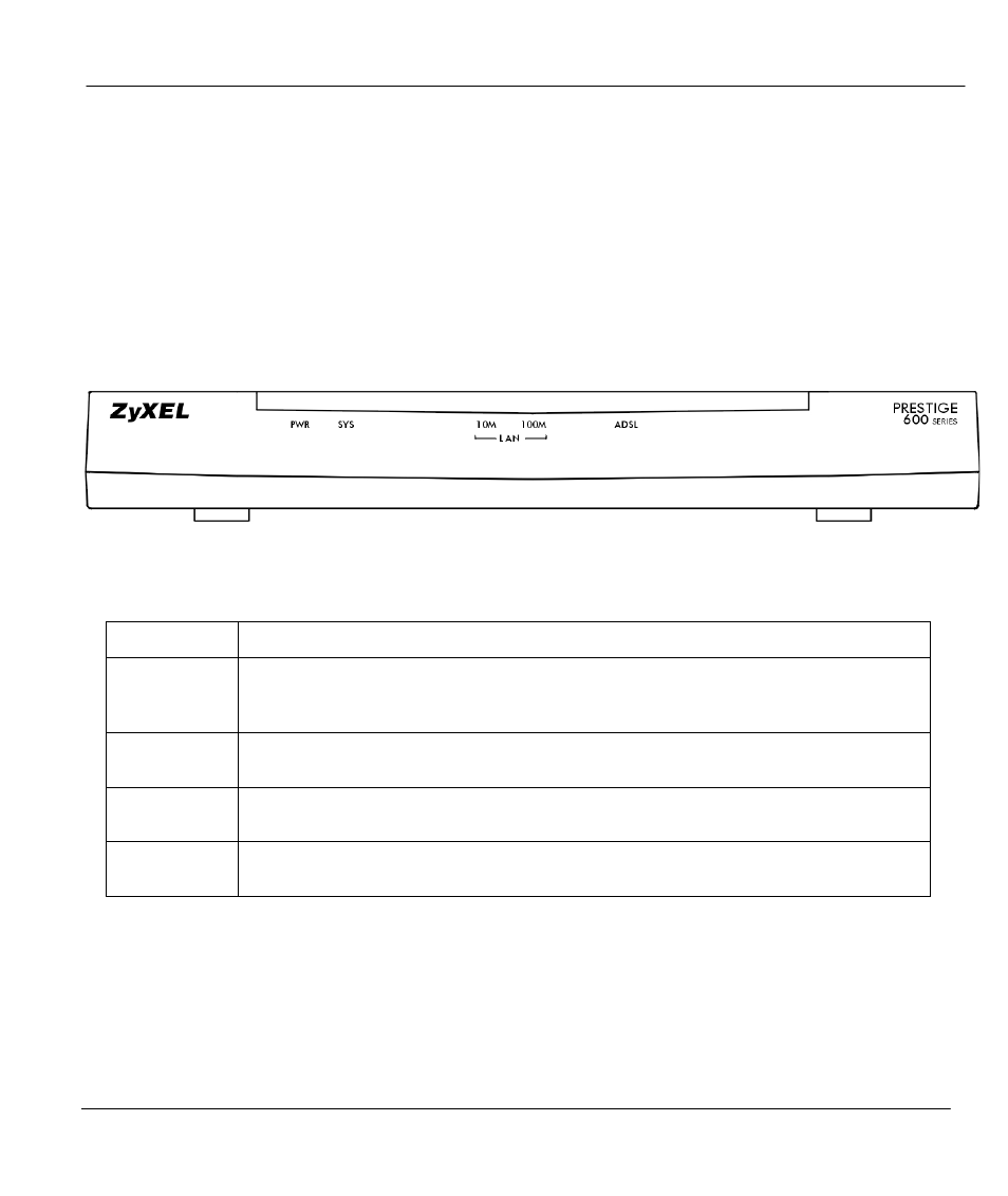
2.1 Front Panel LEDs of the P642R
The LED indicators on the front panel indicate the operational status of the Prestige 642. The table below
the diagram describes the LED functions:
Figure 2-1
Prestige 642R Series Front Panel.
Table 2-1
Front Panel LED Description
PWR
The PWR (power) LED is on when power is applied to the Prestige.
SYS
A steady ‘on’ SYS (system) LED indicates the Prestige is on and functioning
properly while an ‘off’ SYS LED indicates the system is not ready or has a
malfunction. The system is rebooting when the SYS LED is blinking.
LAN 10M
A steady light indicates a 10Mb Ethernet connection. The LED will blink when data
is being sent/received.
LAN 100M
A steady light indicates a 100Mb Ethernet connection. The LED will blink when data
is being sent/received.
ADSL
The ADSL LED is on when the Prestige is connected successfully to a DSLAM. The
LED blinks when data is being sent/received. The LED is off when the link is down.
2.2 Rear Panel and Connections of the Prestige 642R
The following figure shows the rear panel connectors of your Prestige: