2 front panel – ZyXEL Communications PES-1014 User Manual
Page 24
PES-1014 User’s Guide
3-4
Getting Started
Table 3-1 Information Descriptions
LINK
DESCRIPTION
System
Use to view general system information and set related system functions.
Port
Use to view information about the main functions and status of each port and set
individual port functions.
Trunk
Use to view trunk status, and set trunk configuration and mapping.
VLAN
Use to display VLAN status and edit VLAN setup
Forwarding DB
Use to display status of the forwarding data base and edit entries
Stastics
Use to view the statistical contents of each port and host
STP
Use to edit switch and port parameters
Reset
Use to reset counters and factory defaults or restart the switch.
Account
Use to view and add/delete accounts or change passwords.
3.4.2 Front
Panel
Figure 3-8 Switch Icon
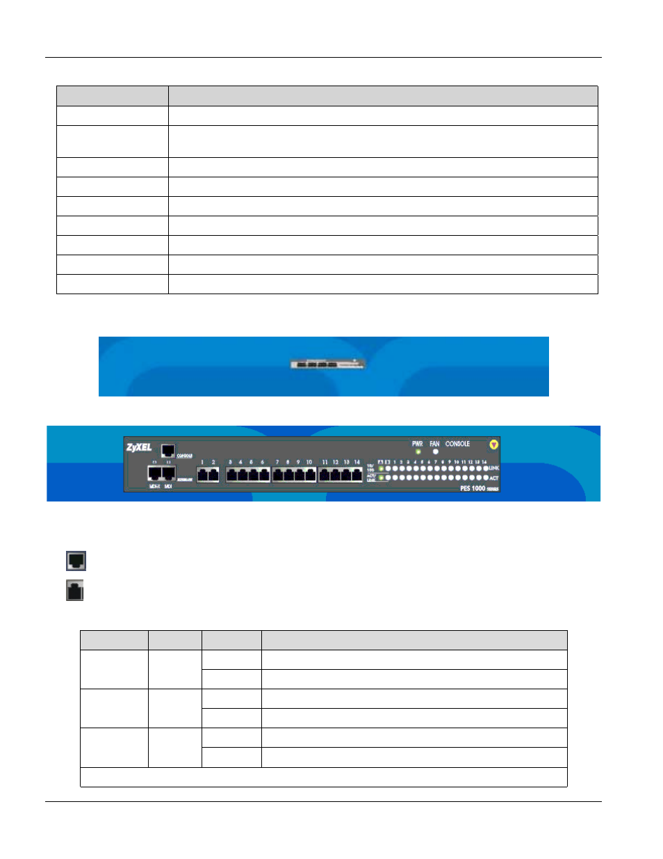
Figure 3-9 Front Panel
On the front of the switch, we see different ports and LEDs.
•
Represents an Ethernet port.
•
Represents an RJ-11 Port
Table 3-2 Manager Front Panel LEDs
LED
COLOR
STATUS
DESCRIPTION
On
The PES-1014 is receiving power.
PWR
Green
Off
The PES-1014 is not receiving power.
On
The fan is malfunctioning.
FAN
Orange
Off
The fan is operating normally
On
The CONSOLE port is connected.
CONSOLE
Green
Off
The CONSOLE port is not connected.
A, B (these are the Ethernet ports)