The front and rear panels – TANDBERG ENTRYPOINT User Manual
Page 13
D 14050.04
10.2007
13
Table of
Contents
Trademarks &
Copyright
Patents &
Disclaimers
Safety/
Environmental
To Get You
Up and Going
Using the
Entrypoint
Viewing the
System Status
Configuring
the Entrypoint
Maintenance
& Upgrade
Services
Dial Plan
Examples
Contact
Information
To Get You
up and Going
TANDBERG
ENTRYPOINT
USER GUIDE
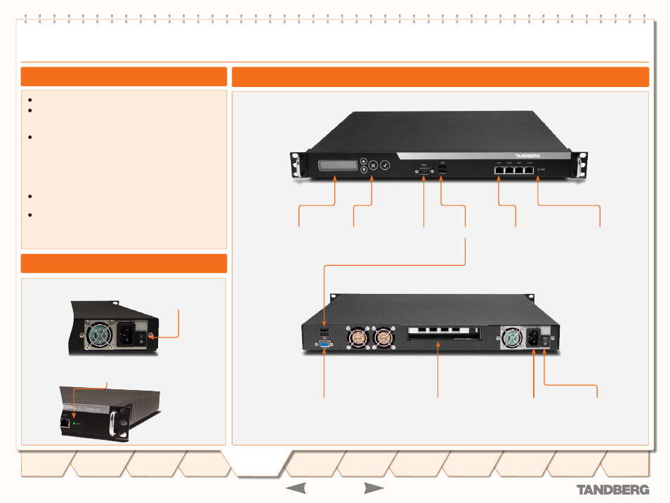
Entrypoint Start-up
LCD panel
Control buttons
RS 232 interface
LAN interface
USB interface
Power On/Off
indicator
1 PRI interface
or
4 BRI interfaces
depending on the configuration ordered,.
VGA connector
Power connector
Power switch
•
Green
: Normal operation.
•
Red Alarm
or Loss of Signal (LoS) indicates that there is no
signal and thus no framing information received. A defective
or unplugged PRI cable will produce the same effect.
•
Yellow Alarm
or
Remote Alarm Indicator
(RAI) means that
the Entrypoint is receiving framing info, but in this framing
info the other side tells the Entrypoint that it is not reading
the Gateway’s transmitted framing information. Typically, this
may be a broken connector in the transmit (TX) part of the
PRI cable. This could also indicate weak or noisy signal in the
transmit (TX) part of the PRI cable.
•
Blue Alarm
indicates that the received frames are not
synchronized properly.
•
No LED’s illuminate
, indicates that layer one framing is
working (right protocol like for example EURO ISDN selected),
however, there is a problem at layer 2 caused by for example
a CRC4 configuration mismatch.
Connectors, Switches, Display, and Buttons
To start the Entrypoint, simply connect the power cable, and
press the power switch button at the back side to position
1
.
On the front panel of the system the power indicator LED,
marked
Pwr
, will turn
GREEN
.
Power switch
The Front and Rear Panels
About the Rear Panel LED Operation