Rear panel, Getting to know the av controller —continued – Onkyo PR-SC885 User Manual
Page 11
11
Getting to Know the AV Controller
—Continued
A
REMOTE CONTROL
This
(Remote Interactive) jack can be con-
nected to the
jack on another
-capable
Onkyo component for remote and system control.
To use
, you must make an analog audio connec-
tion (RCA) between the AV controller and the other
component, even if they are connected digitally.
B
RS232
This port is for connecting the AV controller to
home automation equipment and external control-
lers.
C
PHONO IN
This audio input is for connecting a turntable.
D
COMPONENT VIDEO IN 1, 2, and 3
These RCA component video inputs are for con-
necting components with a component video output,
such as a DVD player, DVD recorder, or DVR (dig-
ital video recorder). They’re assignable, which
means you can assign each one to an input selector
to suit your setup. See “Component Video Input
Setup” on page 48.
E
COMPONENT VIDEO MONITOR OUT 1
This RCA component video output is for connect-
ing a TV or projector with a component video input.
F
COMPONENT VIDEO MONITOR OUT 2/
ZONE 2 OUT
This RCA component video output is for connect-
ing a TV or projector with a component video input
located in your main listening room or Zone 2.
G
HDMI IN 1–4, OUT MAIN, and OUT SUB
HDMI (High Definition Multimedia Interface) con-
nections carry digital audio and digital video.
The HDMI inputs are for connecting components
with an HDMI output, such as a DVD player, DVD
recorder, or DVR (digital video recorder). They’re
assignable, which means you can assign each one to
an input selector to suit your setup. See “HDMI
Input Setup” on page 47.
The HDMI outputs are for connecting a TV or pro-
jector with an HDMI input.
H
SIRIUS antenna
This jack is for connecting a SIRIUS digital
antenna, sold separately (see page 67).
I
XM antenna
This jack is for connecting an XM Mini-Tuner and
Home Dock, sold separately (see page 62).
J
MONITOR OUT
The S-Video or composite video jack should be
connected to a video input on your TV or projector.
K
ZONE 2 OUT
This composite video output can be connected to a
video input on a TV in Zone 2.
L
IR IN A/B and OUT
A commercially available IR receiver can be con-
nected to the IR IN A or B jack, allowing you to
control the AV controller while you’re in Zone 2, or
control it when it’s out of sight, for example,
installed in a cabinet.
A commercially available IR emitter can be con-
nected to the IR OUT jack to pass IR (infrared)
remote control signals through to other components.
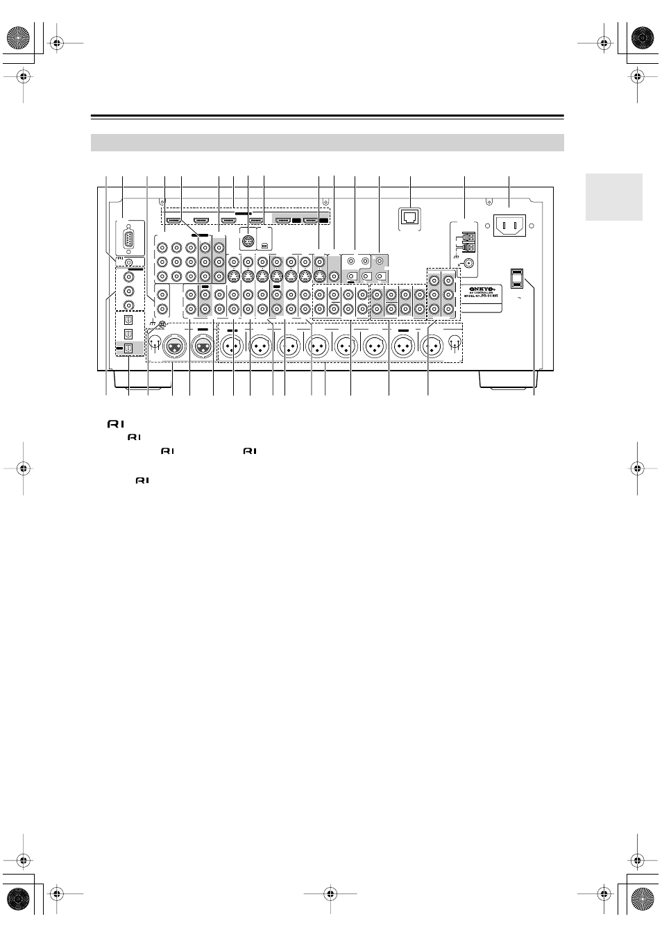
Rear Panel
IN
PHONO
L
L
R
R
RS232
DIGITAL
COAXIAL
OPTICAL
REMOTE
CONTROL
IN 1
IN 1
IN 2
IN
IN
IN
CD
TAPE
AUX 1
GAME/TV
GAME/TV CBL/SAT
CBL/SAT
AUX 1
VCR/DVR
VCR/DVR
DVD
DVD
GND
IN 2
IN 3
V
S
ASSIGNABLE
(DVD)
(CBL/SAT)
(VCR/DVR)
(GAME/TV)
(CD)
COLD
HOT
GND
1
2
3
OUT
HDMI
IN 1
IN 2
IN 3
IN 4
ASSIGNABLE
OUT
MAIN
OUT
SUB
COMPONENT VIDEO
ASSIGNABLE
IN 3
Y
C
B
/P
B
C
R
/P
R
IN 2
IN 1(DVD)
MONITOR
OUT 1
OUT
IN
IN
OUT
IN
IN
FRONT
FRONT
CENTER
SUBWOOFER
SUBWOOFER
CENTER
SURR
SURR
MULTI CH
PRE OUT
SURR BACK
SURR BACK
ETHERNET
ZONE 2
ZONE 3
PRE OUT
L
R
SW
A
B
IR
12V TRIGGER OUT
IN
A
B
OUT
V
S
MONITOR
OUT
ZONE 2
OUT
C
INPUT
BALANCE R
FRONT R
FRONT L
SURR R
CENTER
SURR L
PRE OUT
SUBWOOFER
SURR BACK R
Bi-AMP
BALANCE L
MONO
SURR BACK L
Bi-AMP
COLD
HOT
GND
1
2
3
MONITOR OUT 2
/ZONE 2 OUT
SIRIUS
XM
AC OUTLET
AC INLET
AC 120V
SWITCHED
120W 1A MAX.
60Hz
AM
ANTENNA
FM
75
HD RADIO
R S
8 9
6
4 5
J
M
2
1
P
O
N
Q
3
7
K L
f
T U V W
YZ
c
d
e
a b
X