4 switches and leds, Operational specifications – Renesas M3A-HS37 User Manual
Page 50
Operational Specifications
3.2.4 Switches and LEDs
Rev.1.00 Oct 09, 2008
3-20
REJ11J0021-0100
3
3.2.4 Switches and LEDs
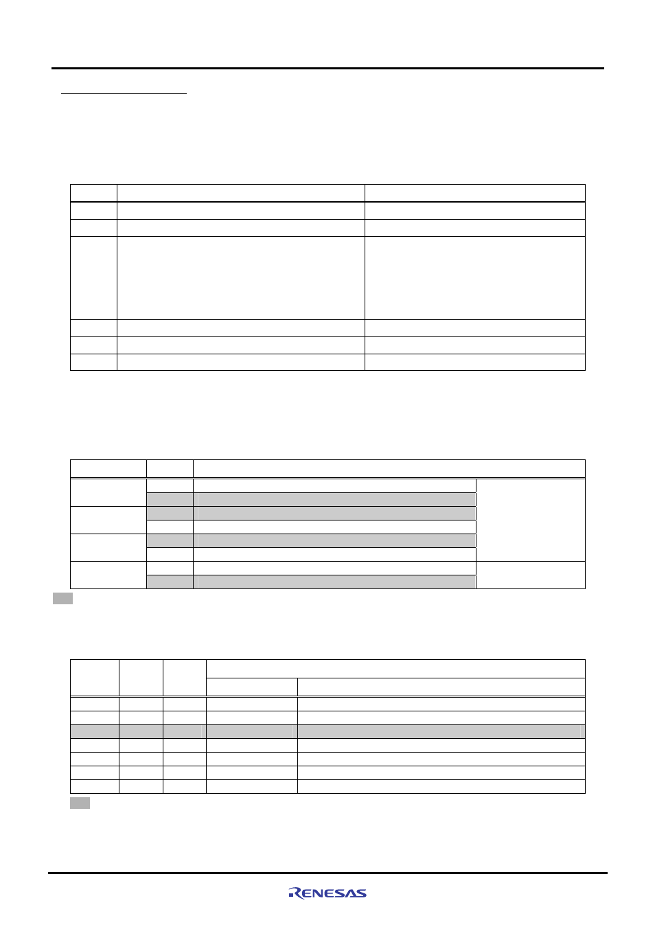
The M3A-HS37 is provided with six switches and seven LEDs.
Table 3.2.4 lists switches on the M3A-HS37.
Table 3.2.4 Switches on the M3A-HS37
No. Function
Remarks
SW1
System power on/off switch
-
SW2
System reset input switch
Refer to Section 2.9 for details.
SW3
User DIP switches (4/package)
SW3-1 OFF: PF12 = ”H” ON: PF12 = ”L”
SW3-2 OFF: PF13 = ”H” ON: PF13 = ”L”
SW3-3 OFF: PF14 = ”H” ON: PF14 = ”L”
SW3-4 OFF: PF15 = ”H” ON: PF15 = ”L”
PF12,PF13,PF14, and PF15 are pulled up.
Refer to Section 2.5 for details.
SW4
System setting DIP switches (4/package)
Refer to Table 3.2.5 for the functions
SW5
NMI input switch
Refer to Section 2.10 for details.
SW6
IRQ2 input switch
Refer to Section 2.10 for details.
Table 3.2.5 lists the functions of the switch (SW4). The SH7137 operating mode is set by the combinations of the pins FEW,
MD0, and MD1. Table 3.2.6 lists the SH7137 operating mode setting.
Table 3.2.5 Functions of Switch (SW4)
No. Setting
Function
OFF
FWE="H" (On-chip flash memory is write- and erase-protected)
SW4-1
FWE
ON
FWE="L" (On-chip flash memory is write- and erase-enabled)
OFF
MD1 pin state is "H"
SW4-2
MD1
ON
MD1 pin state is "L"
OFF
MD0 pin state is "H"
SW4-3
MD0
ON
MD0 pin state is "L"
Operating mode setting
(Refer to Table 3.2.6)
OFF
LED Vcc OFF
SW4-4
LED
ON
LED Vcc ON
indicates the default setting.
Note: Refer to Figure 2.5.1 for LED Vcc.
Table 3.2.6 SH7137 Operating Mode Setting
SH7137 Operating Mode
SW4-1
(FWE)
SW4-2
(MD1)
SW4-3
(MD0)
No. Name
ON
ON
ON
Mode 0
MCU expansion mode 0 (On-chip ROM disabled, CS0 space: 8-bit bus)
ON
OFF
ON
Mode 2
MCU expansion mode 2 (On-chip ROM enabled, CS0 space: 8-bit bus)
ON
OFF
OFF
Mode 3
Single chip mode (On-chip ROM enabled)
OFF ON ON
Mode
4
*
Boot mode (On-chip ROM enabled)
OFF ON OFF
Mode
5
*
User boot mode (On-chip ROM enabled, CS0 space: 8-bit bus)
OFF OFF ON
Mode
6
*
User program mode (On-chip ROM enabled, CS0 space: 8-bit bus)
OFF OFF OFF
Mode
7
*
User program mode (On-chip ROM enabled)
Indicates the default setting.
Note: These are the programming mode of the flash memory