9 reset module, 10 interrupt switches, Functional specifications – Renesas M3A-HS37 User Manual
Page 29
Functional Specifications
2.9 Reset Module
Rev.1.00 Oct 09, 2008
2-13
REJ11J0021-0100
2
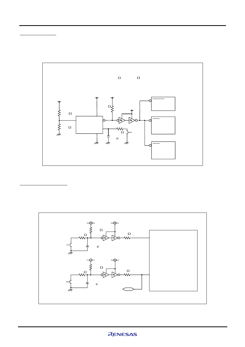
2.9 Reset Module
The reset circuit controls the SH7137 reset signals on the M3A-HS37.
Figure 2.9.1 shows the M3A-HS37 reset module block diagram.
CPU-VCC
Delay capacity
Input
Output
Ra
M51957BP
SH7137
Rb
CPU-VCC
Cd
0.1 F
Reset
switch
(SW2)
RES
RESET
Expansion connector
Reset IC output delay time: td = 0.34 x Cd (pF) = 34 ms
Reset IC output detection voltage: Ra = 10 K , Rb = 10 K
Vs = 1.25 x (Ra+Rb)/Rb = 2.5 V
Open collector
output reset IC
H-UDI connector (14-pin)
RES
CPU-VCC
10 K
10 K
100
4.7 K
CPU-VCC
Figure 2.9.1 Reset Module Block Diagram
2.10 Interrupt Switches
The M3A-HS37 is provided with two push-button switches (NMI switch and IRQ2 switch) for the NMI pin and IRQ2 pin of the
SH7137.Figure 2.10.1 shows the interrupt switch block diagram.
PB4/A18/IRQ2/POE4/TIC5US
NMI
SW
SH7137
CPU-VCC
SW
CPU-VCC
NMI switch
IRQ2 switch
Expansion
connector
10 K
10 K
220
220
2.2 F
2.2 F
0
0
CPU-VCC
CPU-VCC
Figure 2.10.1 Interrupt Switch Block Diagram