6 power supply module, Sh7137, Functional specifications – Renesas M3A-HS37 User Manual
Page 26
Functional Specifications
2.6 Power Supply Module
Rev.1.00 Oct 09, 2008
2-10
REJ11J0021-0100
2
2.6 Power Supply Module
The M3A-HS37 is supplied +5 V power and the voltage regulator on the board generates +3.3 V. LM2738YMY is the output
voltage adjustable regulator and the desired voltage value can be generated by changing the resistance value. +5 V power is
supplied from the DC regulated power supply (via the power connector, J4) or AC adapter (via the DC power jack, J7).
The SH7137 system power supply (VCC) can be switched to +3.3 V or +5 V by 3V/5V select jumper (JP1) setting (default: 5V).
When switching the VCC, note that the following:
・The conversion voltages between 5 V and 3 V are supplied to the RCAN interface as appropriate.
・Both +5 V and +3 V are available on the CPU and SRAM (part number: 5M5256DFP-VP70GI).
・The supply voltage supplied to the CPU is also supplied to SRAM.
・Always +5 V is supplied to the SH7137 A/D converter.
The SH7137 system power supply (VCC), A/D power supply (AVCC), and AVREF power supply can be supplied from external
power supply, respectively.
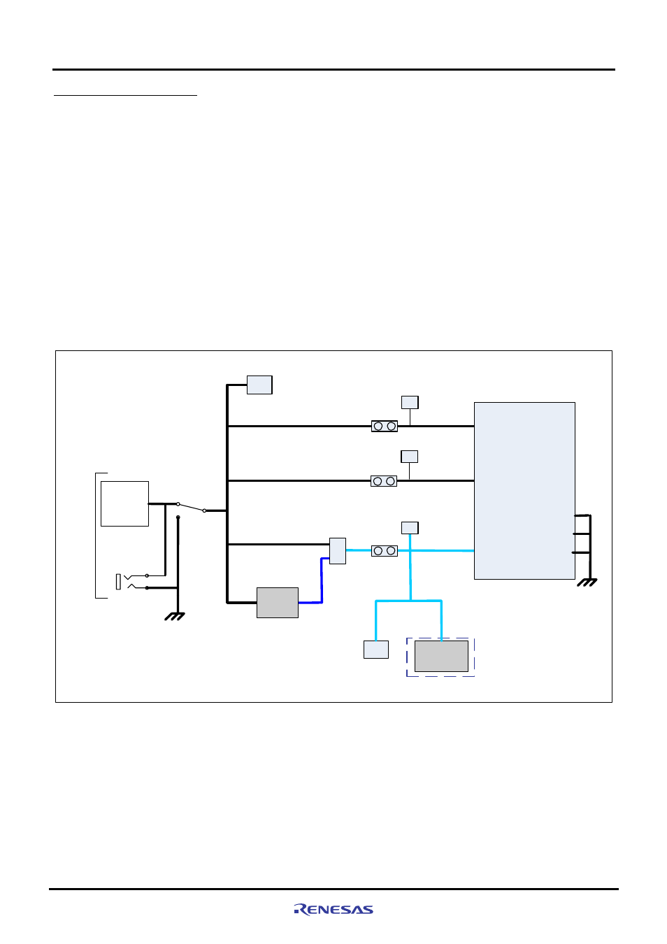
Figure 2.6.1 shows the M3A-HS37 power circuit block diagram.
J4
Power
supply
connector
Expansion connector
Power switch
External
power supply
5 VCC
5 VCC
3 VCC
5 V to
3.3 V
CPU-VCC
VCC
AVCC
SH7137
SRAM
5 VCC
AVREFH
J8 connector
Expansion connector
5 VCC
AVCC
AVREF
J8 connector
JP4
JP5
JP
JP2
Optional
CPU power supply
select jumper (JP1)
J7
DC power jack
5V DC
Input
VCC
2
1
3
AVREFL
VSS
AVSS
Figure 2.6.1 Power Supply Circuit Block Diagram