NEC NEAX IPS NWA-008869-001 User Manual
Page 57
CHAPTER 2 INSTALLATION
– 47 –
NWA-008869-001 Rev.1.0
atch2001.fm
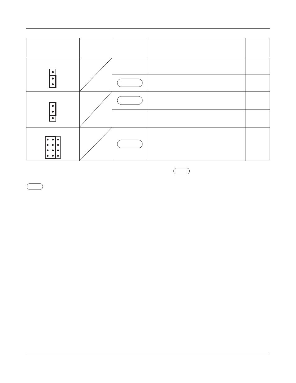
The figure in the SWITCH NAME column and the position of
in the SETTING POSITION col-
umn indicate the standard setting of the switch. When the switch is not set as shown by the figure and
, the setting of the switch varies with the system concerned.
NOTE 1:
Set the groove on the switch to the desired position.
NOTE 2:
When the power is on, flip the MB switch to ON (UP position) before plugging/unplugging the
circuit card.
NOTE 3:
To receive a clock signal from MP card, set the SW0-1 and SW0-2 on all the DTI cards to
“OFF”.
NOTE 4:
This card must be reset after the SW0-3 to SW0-7 switch settings. Set the MB switch to UP and
then DOWN.
SWITCH NAME
SWITCH
NUMBER
SETTING
POSITION
FUNCTION
CHECK
MAS (Jumper pin)
UP
Clock Source
Clock Receiver
AISS (Jumper pin)
AIS signal is sent out when make-busy
or power on.
DOWN
AIS signal is not sent out when make-
busy or power on.
JP1 (Jumper pin)
Always set to LEFT
DOWN
UP
LEFT
INSTALLATION PROCEDURE