Nortel Networks Server 1005r User Manual
Page 32
32
Chapter 4 Installing the server and peripheral devices
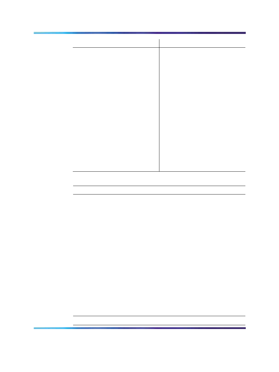
Label
Control or feature
Label
Control or feature
B1
PCI card #3 dual NIC for
HA configuration. For more
information about HA, see High
Availability: Installation and
Configuration (NN44200-311).
H
RJ45 NIC 1 connector
B2
PCI card #2 dual NIC for High
Availability (HA) configuration.
For more information about
HA, see High Availability:
Installation and Configuration
(NN44200-311).
I
RJ45 NIC 2 connector
B3
RAID
J
Video connector
C
PCI full-size card brackets.
Numbered (1, 2, 3) from top to
bottom.
K
USB 1
D
Power Supply 1
L
USB 0
E
Power Supply 2
M
Server management LAN port
F
PS/2 mouse and keyboard
connectors
N
External SCSI tape drive
To connect the mouse, keyboard, and monitor to the server
Step
Action
1
Place the monitor, keyboard, and mouse in the same location as
the server.
2
Plug the keyboard and mouse cables into the PS/2 connectors on
the rear panel (see
"Rear panel connectors" (page 31)
).
3
Plug the monitor into the video connector on the rear panel. Tighten
the screws on the connector.
4
Ensure that a single-point ground reference is available for all
the power outlets serving the CallPilot server and its peripherals.
Before the CallPilot server installation, a qualified electrician must
implement the single-point ground reference requirement between
the power outlets of the CallPilot server and the power outlets of
the switch.
5
Connect the power cord to the monitor and plug the other end into
a wall receptacle or power bar.
6
Turn on the monitor.
—End—
Nortel CallPilot
1005r Server Hardware Installation
NN44200-308
01.06
Standard
5.0
15 May 2008
Copyright © 2006-2008, Nortel Networks
.