Analog output, Analog output circuitry, Figure 4-5. analog output circuitry – National Instruments DAQCard-1200 User Manual
Page 64: Analog output -11, Analog output circuitry -11, Figure 4-5
Chapter 4
Theory of Operation
© National Instruments Corporation
4-11
Analog Output
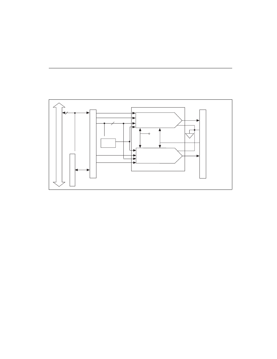
The DAQCard-1200 has two channels of 12-bit D/A output. Each analog
output channel can provide unipolar or bipolar output. The DAQCard-1200
also contains timing circuitry for waveform generation timed either
externally or internally. Figure 4-5 shows the analog output circuitry.
Figure 4-5. Analog Output Circuitry
Analog Output Circuitry
Each analog output channel contains a 12-bit DAC. The DAC in each
analog output channel generates a voltage proportional to the 5 V reference
(provided in the Dual DAC chip) multiplied by the 12-bit digital code
loaded into the DAC. The voltage output from the two DACs is available
at the DAQCard-1200 I/O connector DAC0OUT and DAC1OUT pins.
You can program each DAC channel for a unipolar voltage output or a
bipolar voltage output range. A unipolar output gives an output voltage
range of 0 to +10 V. A bipolar output gives an output voltage range of ±5 V.
For unipolar output, 0 V output corresponds to a digital code word of 0. For
bipolar output, –5 V output corresponds to a digital code word of F800 hex.
One LSB is the voltage increment corresponding to an LSB change in the
digital code word. For both outputs:
DAC0
DAC1
DAC0OUT
AGND
DAC1OUT
EXTUPDATE*
5 V Internal
Reference
DAC0WRT
Data
DAC1WRT
Counter
A2
External Update
8
I/O Connector
Decode Cir
cuitr
y
Dat
PCMCIA I/O Channel Interface
PCMCIA Interface
Two
'
s Complement
Two's Complement
Dual DAC Chip
Control
Signal
1 LSB
10 V
4,096
--------------
=