Figure 3-14. pretrigger daq timing, Figure 3-14, Pretrigger daq timing -24 – National Instruments DAQCard-1200 User Manual
Page 46
Chapter 3
Signal Connections
3-24
© National Instruments Corporation
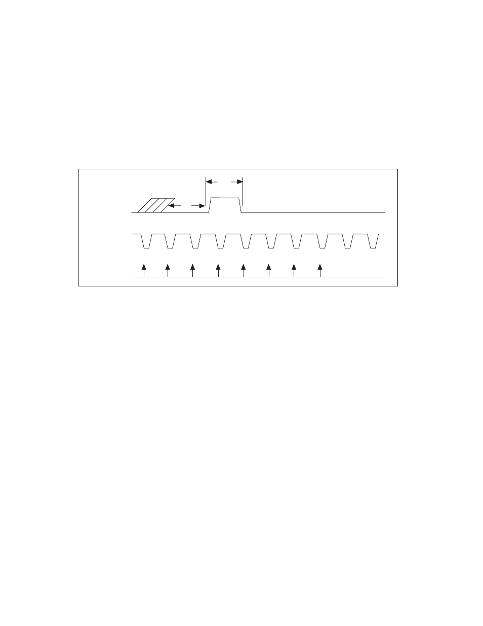
Figure 3-14 shows a pretrigger data acquisition timing sequence using
EXTTRIG and EXTCONV*. The data acquisition operation has been
initiated through software. Notice that the sample counter has been
programmed to allow five conversions after the rising edge on the
EXTTRIG signal. Additional transitions on the EXTTRIG line have no
effect until you initiate a new data acquisition sequence.
Figure 3-14. Pretrigger DAQ Timing
Because both pretrigger and posttrigger modes use EXTTRIG input, you
can only use one mode at a time.
For interval scanning data acquisition, counter B1 determines the scan
interval. Instead of using counter B1, you can externally time the scan
interval through OUTB1. If you externally time the sample interval, you
should also externally time the scan interval.
Figure 3-15 shows an example of a multiple-channel interval-scanning data
acquisition operation. The scan interval and the sample interval are being
timed externally through OUTB1 and EXTCONV*. Channels 1 and 0 of
the input multiplexers are being scanned once during each scan interval.
The first rising edge of EXTCONV* must occur a minimum of 50 ns after
the rising edge on OUTB1. The first rising edge of EXTCONV* after the
rising edge of OUTB1 enables an internal GATE signal that allows
conversions to occur. The first conversion then occurs on the following
falling edge of EXTCONV*.
tw 50 ns minimum
EXTTRIG
EXTCONV*
CONVERT
VIH
VIL
tw
tw