Analog input circuitry, Figure 4-4. analog input circuitry, Analog input circuitry -6 – National Instruments DAQCard-1200 User Manual
Page 59: Figure 4-4
Chapter 4
Theory of Operation
4-6
© National Instruments Corporation
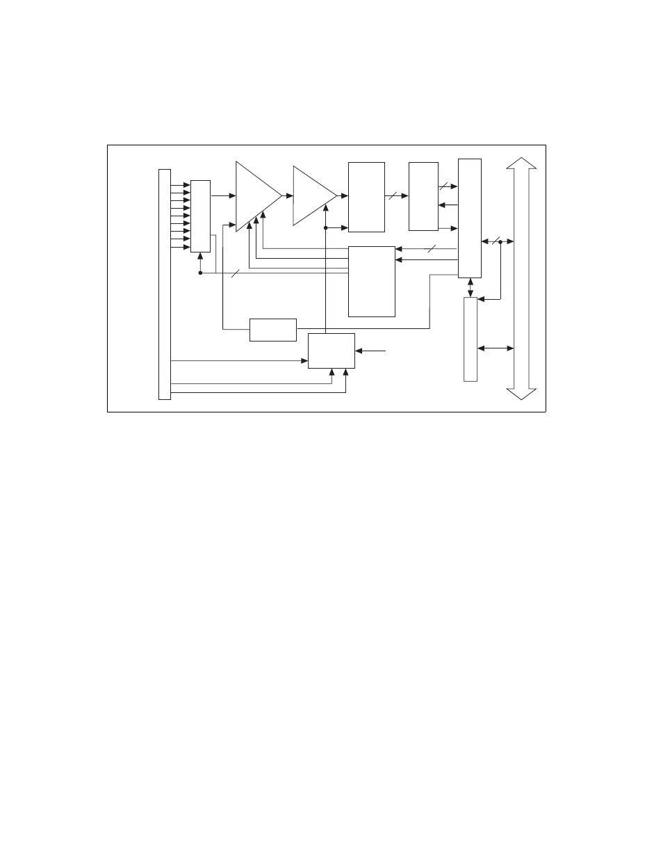
Figure 4-4. Analog Input Circuitry
Analog Input Circuitry
The analog input circuitry consists of two analog input multiplexers, mux
counter/gain select circuitry, a software-programmable gain amplifier, a
12-bit ADC, and a 12-bit FIFO memory that is sign-extended to 16 bits.
The two input multiplexers route the input channels to the instrumentation
amplifier in either RSE, NRSE, or DIFF mode. The input multiplexers
provide input overvoltage protection of ±35 V powered on and ±25 V
powered off.
The mux counters control the input multiplexers. The DAQCard-1200
can perform either single-channel data acquisition or multiple-channel
(scanned) data acquisition. These two modes are software selectable.
For single-channel data acquisition, you select the channel and gain before
initiating data acquisition. These gain and multiplexer settings remain
constant during the entire data acquisition process. For multiple-channel
data acquisition, you select the highest numbered channel and gain before
data acquisition is initiated. Then the mux counter decrements from the
highest numbered channel to channel 0 and repeats the process. Thus you
Sample-
and-Hold
Amp
DAQ
Timing
Gain Select/
Mux Counter
Mux
Pro-
grammable
Gain Amp
12-Bit
ADC
1k
Sample
A/D
FIFO
External Trigger
Counter/Timer
Signals
WRT/RD
CON
V
EXTCONV*
OUTB1
EXTTRIG
ACH0
ACH1
ACH2
ACH3
ACH4
ACH5
ACH6
ACH7
12
12
8
6
A/D
Data
Data
Data
I/O Connector
GAIN0
GAIN1
GAIN2
Con
v
e
rt
AISENSE/
AIGND
PCMCIA I/O Channel
8
Data
External Convert
Output B1
PCMCIA Interface
Decode Cir
cuitr
y
Dither
Circuitry
Dither Enable
Dither