Signal connection descriptions, Signal connection descriptions -3 – National Instruments DAQCard-1200 User Manual
Page 25
Chapter 3
Signal Connections
© National Instruments Corporation
3-3
Signal Connection Descriptions
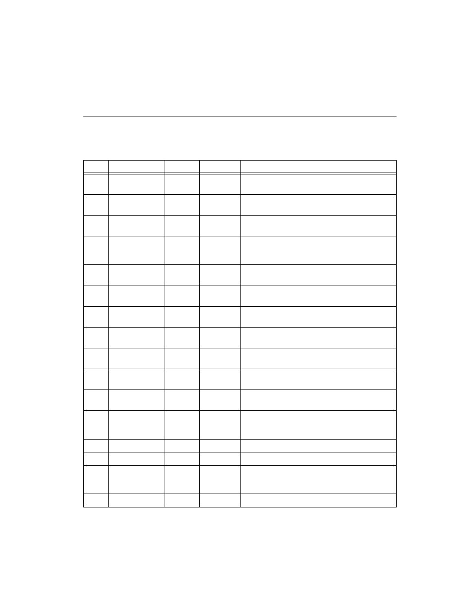
The following table describes the connector pins on the DAQCard-1200
front I/O connector by pin number and gives the signal name and the
significance of each signal connector pin.
Pins
Signal Name
Direction
Reference
Description
1–8
ACH<0..7>
AI
AGND
Analog Channel 0 through 7—Analog input channels 0
through 7.
9
AISENSE/AIGND
AI
AGND
Analog Input Sense/Analog Input Ground—Connected to
AGND in RSE mode, analog input sense in NRSE mode.
10
DAC0OUT
AO
AGND
DAC0 Output—Voltage output signal for analog output
channel 0.
11
AGND
N/A
N/A
Analog Ground—Analog output ground reference for
analog output voltages. This signal is the bias current return
point for differential measurements.
12
DAC1OUT
AO
AGND
DAC1 Output—Voltage output signal for analog output
channel 1.
13
DGND
N/A
N/A
Digital Ground—Voltage ground reference for the digital
signals and the +5 V supply.
14–21
PA<0..7>
DIO
DGND
Port A 0 through 7—Bidirectional data lines for port A.
PA7 is the MSB, and PA0 is the LSB.
22–29
PB<0..7>
DIO
DGND
Port B 0 through 7—Bidirectional data lines for port B.
PB7 is the MSB, and PB0 is the LSB.
30–37
PC<0..7>
DIO
DGND
Port C 0 through 7—Bidirectional data lines for port C.
PC7 is the MSB, and PC0 is the LSB.
38
EXTTRIG
DI
DGND
External Trigger—External control signal to trigger a
DAQ operation.
39
EXTUPDATE*
DI
DGND
External Update—External control signal to update
DAC outputs.
40
EXTCONV*
DIO
DGND
External Convert—External control signal to time
A/D conversions (DI) and drive SCANCLK when you use
SCXI (DO).
41
OUTB0
DO
DGND
Output B0—Voltage output signal of counter B0.
42
GATB0
DI
DGND
Gate B0—External control signal for gating counter B0.
43
OUTB1
DIO
DGND
Output B1—Voltage output signal of counter B1 when
selected as output (DO). This is the external control signal
for timing an interval cycle when selected as input (DI).
44
GATB1
DI
DGND
Gate B1—External control signal for gating counter B1.