Troubleshooting, Gas valve adjustment procedure – Lochinvar Shield SNR150-100 User Manual
Page 73
73
13
Troubleshooting
(continued)
Gas valve adjustment procedure
If adjustment of the gas valve is deemed necessary, use the
following procedures: (Note: The procedures below are
model specific.)
Models SNR150-100 -- SNA285-125
Locate the throttle adjustment screw on the side of the
venturi valve (FIG. 13-2). Using a screwdriver, turn the screw
a 1/4 turn clockwise to decrease CO
2
levels or a 1/4 turn
counterclockwise to increase CO
2
levels. After performing
one adjustment on the valve, follow the Combustion Analysis
Procedure on page 72 of this manual to measure the
combustion.
If combustion is still not within the specified range, repeat
the procedure. This procedure SHOULD NOT be performed
more than four (4) times. If after four (4) adjustments and
the combustion is still not within the specified range, revisit
the possible causes in Table 13F on page 72 or replace the
gas valve.
THROTTLE
ADJUSTMENT
SCREW
Figure 13-2 Gas Valve Adjustment: Models
SNR150-100 -- SNA285-125
THROTTLE
ADJUSTMENT
SCREW
Figure 13-4 Gas Valve Adjustment: Model SNA500-125
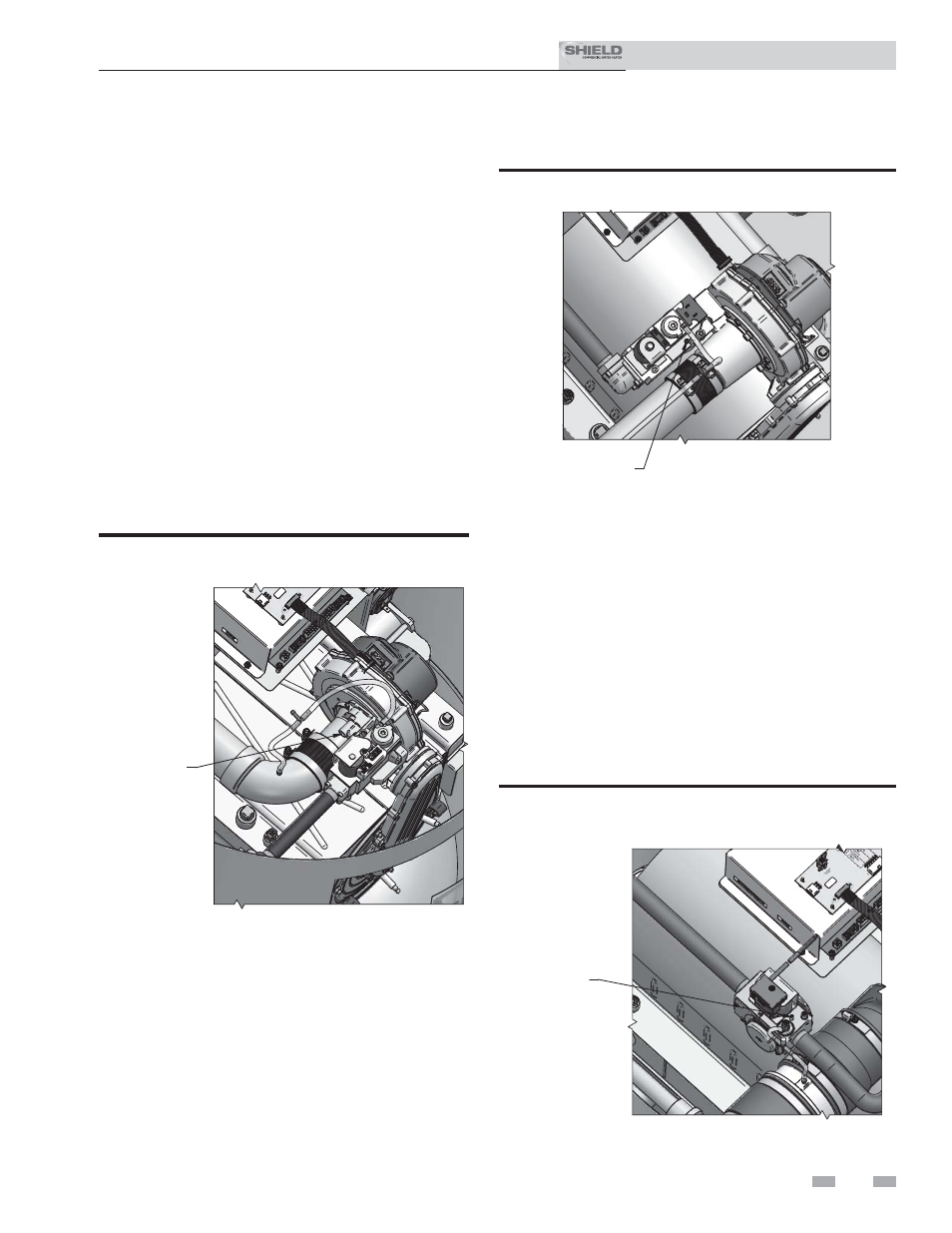
Model SNA400-125
Locate the throttle adjustment screw on the top of the gas
valve, see FIG. 13-3. Using a screwdriver, turn the screw 1/8
turn counterclockwise to increase CO
2
levels or 1/8 turn
clockwise to decrease CO
2
levels. After one adjustment on
the valve, follow the Combustion Analysis Procedure on page
72 of this manual to measure the combustion.
If combustion is still not within the specified range, repeat
the procedure. This procedure SHOULD NOT be performed
more than four (4) times. If after four (4) adjustments and
the combustion is still not within the specified range, revisit
the possible causes in Table 13F on page 72 or replace the gas
valve.
Model SNA500-125
Locate the throttle adjustment screw on top of the gas valve,
see FIG. 13-4. Using a screwdriver, turn the screw a 1/4 turn
counterclockwise to increase CO
2
levels or a 1/4 turn clockwise
to decrease CO
2
levels. After one adjustment on the valve, follow
the Combustion Analysis Procedure on page 72 of this manual
to measure the combustion.
If combustion is still not within the specified range, repeat
the procedure. This procedure SHOULD NOT be performed
more than four (4) times. If after four (4) adjustments and the
combustion is still not within the specified range, revisit the
possible causes in Table 13F on page 72 or replace the gas valve.
THROTTLE
ADJUSTMENT
SCREW
Figure 13-3 Gas Valve Adjustment: Model SNA400-125
Installation & Service Manual
TM