Troubleshooting, Combustion analysis procedure – Lochinvar Shield SNR150-100 User Manual
Page 72
72
13
Troubleshooting
Combustion Analysis Procedure
1. Press the SHUTDOWN button on the display until
HTR:Off
appears in the display window.
2. Remove the screws securing the top panel to the unit.
Remove the panel from the unit to gain access to the flue
sensor.
3. Locate the flue sensor in the top of the vent connection.
Remove the flue sensor and grommet from the unit. Note:
Combustion measurements will be made at this point.
4. Press the SHUTDOWN button on the display until
HTR:Standby
appears in the display window.
5. Locate the pinhole button above the “r” in the Lochinvar
logo on the display board (FIG. 11-1). Insert a thin wire
(such as a paper clip) into the hole and press the button
once and hold for 5 seconds to place the water heater into
Service Mode. In Service Mode the water heater will fire at
ignition speed and will then modulate up to full fire.
6. Insert the probe from a combustion analyzer into the hole
left by the removal of the flue temperature sensor.
7. Once the water heater has modulated up to full fire, measure
the combustion. The values should be in the range listed in
Table 13G. The CO levels should be less than 150 ppm for a
properly installed unit.
If the combustion is not within the specified range, reference
the chart below for possible causes and corrective actions.
Table 13F Troubleshooting Chart - Combustion Levels
POSSIBLE CAUSE
CORRECTIVE ACTION
Vent/Air Intake Length
or Obstruction
• Refer to Section 2 - General Venting for the proper venting and air intake methods for the
Shield water heater.
• Check for obstructions at the vent/air intake terminals.
Gas Supply Pressure
• Refer to Section 7 - Gas Connections for the proper gas supply for the Shield water heater.
Dirty/Damaged Burner
• Refer to page 60 of this manual for burner removal and cleaning procedures.
• Replace burner if necessary.
Gas Valve Adjustment
• Refer to page 73 of this manual for the gas valve adjustment procedure.
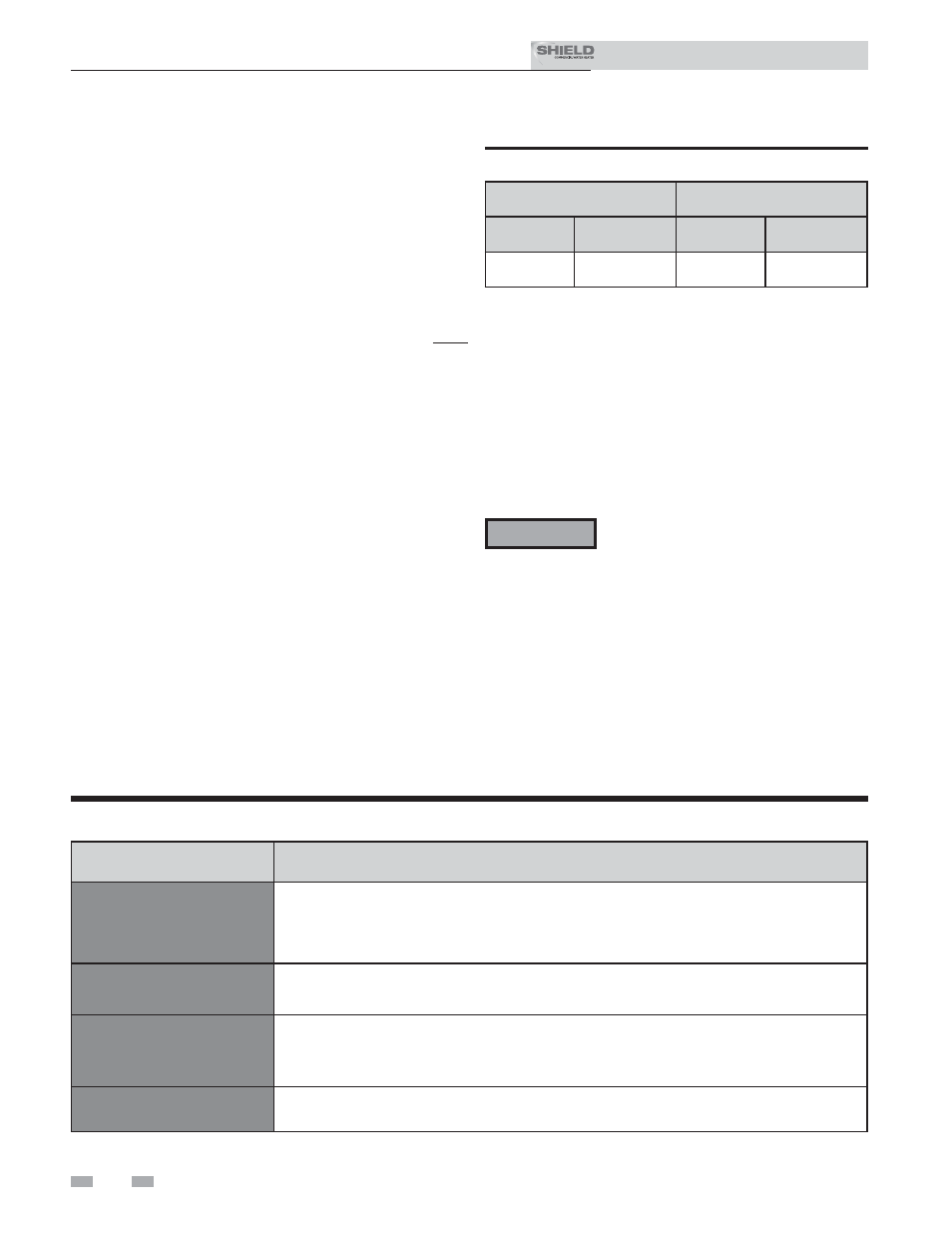
Table 13G Flue Products
Natural Gas
Propane
CO
2
O
2
CO
2
O
2
8.0% - 10%
3.0% - 6.5%
9.0% - 11%
4.1% - 6.9%
8. Once the combustion analysis is complete, press the
SHUTDOWN button on the display board (FIG. 11-1)
to take the water heater out of Service Mode. The
water heater will go to shutdown and the display will
show
HTR:Off
.
9. Replace the flue sensor and grommet into the vent
connection.
10. Replace the top panel on the unit.
11. Place the Shield water heater back into normal operation.
You must replace the flue sensor to
prevent flue gas spillage into the room.
Failure to comply could result in severe
personal injury, death, or substantial
property damage.
ƽ WARNING
Installation & Service Manual
TM