Installing the adat i/o board (dib-8), P.178), Efer to “parts of the dib-8 and their functions – KORG XTENDED DEFINITION D32XD User Manual
Page 188: The optional adat i/o board must be installed, Installation procedure, Parts of the dib-8 and their functions
178
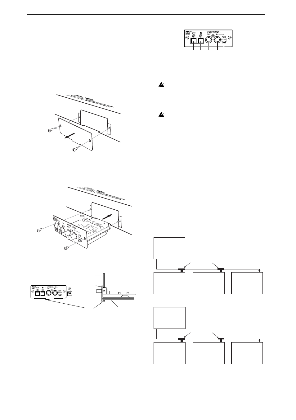
Installing the ADAT I/O board (DIB-8)
An ADAT I/O board (DIB-8) can be installed in the D32XD/
D16XD to add eight channels and word clock in/out of dig-
ital input.
Installation procedure
1. You will need a Philips (+) screwdriver.
2. Turn off the power of the D32XD/D16XD, and discon-
nect all cables.
3. Use the screwdriver to remove the two screws that fas-
ten the DIB-8 cover.
Be careful not to lose the screws you removed.
4. Remove the DIB-8 cover.
5. Install the DIB-8, making sure that the vertical and hor-
izontal alignment are correct.
The side with the components mounted faces up, and the
side with the connector is at the rear.
6. Press the DIB-8 in until its panel touches the rear panel.
Press it down so that the tab at the bottom is below the
bottom panel.
7. Fasten the DIB-8 cover using the two screws that you
removed.
8. When you are finished, turn on the power and verify
that the DIB-8 is installed correctly. (
Parts of the DIB-8 and their functions
1. ADAT output jack
This jack outputs an ADAT format (ADAT Type I/II for-
mat) digital signal of the same sampling frequency and
bit depth as the current song.
96 kHz output is not supported.
2. ADAT input jack
This jack inputs an ADAT format (ADAT Type I/II for-
mat) digital signal of the same sampling frequency and
bit depth as the current song.
96 kHz input is not supported.
3. Word clock output jack
This jack outputs the internal clock as a word clock sig-
nal.
4. Word clock input jack
This jack inputs a word clock signal from an external
device.
5. 75
Ω switch
This switches the 75
Ω word clock terminator on/off.
Turn the switch On if this is the end of the connection, or
Off if the connection is branched.
Word clock connection
When using the D32XD/D16XD as the word clock master
and connecting multiple word clock slave devices to it, use
T-type BNC branching connectors to distribute the word
clock. When using the D32XD/D16XD as a word clock slave,
you will need to set the 75
Ω switch appropriately. Turn this
switch on for the last connected device, and off for devices
from which the word clock is being branched.
If the D32XD/D16XD is transmitting the word clock
(Master)
If the D32XD/D16XD is receiving the word clock (Slave)
D32XD/D16XD
bottom panel
DIB-8 panel
Tab
D32XD/D16XD rear panel
4
5
1
2
3
IN
IN
IN
D32XD [*D16XD]
Master
OUT
Slave device A
Slave device B
Slave device C
75
Ω
switch: off
75
Ω
switch: off
75
Ω
switch: on
T-type BNC connector
IN
IN
IN
Slave device
D32XD [*D16XD]
Master device
OUT
Slave device A
75
Ω
switch: off
75
Ω
switch: off
75
Ω
switch: on
T-type BNC connector
Slave device
D32XD [*D16XD]