3g-2. analog compressor 9–16, Effect, D32xd – KORG XTENDED DEFINITION D32XD User Manual
Page 126: 1. routing a
116
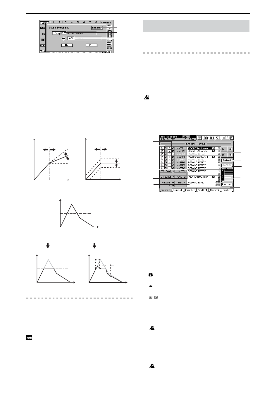
14a. Rename
Renames the comp program.
Press the button to display the Rename dialog box,
and edit the name. You can assign a name of up to
eight characters.
14b. Comp channel cell
Selects the comp channel whose program you want to
save. Press the cell to highlight it, and use the value
dial
(or the +/– keys) to select the comp channel.
14c. Program number cell
[U01…U50]
Selects the save-destination program number. Press
the cell to highlight it, and use the value dial (or the +/
–
keys) to select the program number. The existing
program at that number will be overwritten.
How THRESHOLD, RATIO, and OUT GAIN affect the in-
put
How ATTACK and RELEASE operate
3g-2. Analog Compressor 9–16
This tab page is available if an optional 8-channel analog
compressor board (ACB-8) is installed on the optional 8-
channel analog input board (AIB-8).
This lets you apply compression to the analog inputs from
INPUT jacks 9 through 16.
Comp channels 9–16 correspond to INPUT jacks 9–16; i.e., comp
channel 9 applies to the INPUT 9 jack, and comp channel 10 ap-
plies to the INPUT 10 jack.
For details on the parameters and values, refer to “3g-1. An-
alog Compressor 1–8.”
If the above options are not installed, this tab page cannot be
selected.
D32XD
4-1. Routing A
This lists the effect programs used by the insert 1–8, master,
and final effects, and shows their status.
The D32XD lets you simultaneously use up to 24 insert ef-
fects, two master effects, and one final effect.
Insert effects 9–24 can be viewed and edited in “4-2. Routing
B.”
The number of simultaneously usable effects will differ depending
on the size of the effect programs, and on how they are assigned.
In this screen you can also select effect programs and edit
some of their parameters.
To select a program, use the value dial or press the Select
button in the screen and choose from a list of effect programs
by category.
1. CH
[1…32]
Selects the channel to which each insert effect 1 through 8
will be applied.
2. Insert effect location
[IN, TR]
Selects whether each insert effect 1 through 8 will be
applied to the input (IN) or to the playback track (TR).
3. Insert EFF 1…8
Selects the program for each insert effect 1 through 8. A
maximum of eight different effects can be used.
The cells indicate the currently selected program number,
effect name, effect size icon, control icon (only if speci-
fied), and on/off icon.
The letter “E” is displayed at the beginning of the effect
number to indicate an effect that is being edited.
: Effect size icon
Indicates the DSP size of the effect.
: Control icon
Indicates an effect to which effect control is assigned.
/
: On/off icon
Indicates the on (enabled) or off (disabled) status of
the effect.
For the possible combinations and how they will operate,
refer to “Effects that can be used simultaneously”
(
Due to the input/output structure of the mixer, you cannot use
a stereo program for insert effect 8.
4. MasterEFF 1, 2
Here you can select a program for master effects 1 and 2.
The cells indicate the currently selected program number,
effect name, effect size, control icon (only if specified),
and on/off icon.
You cannot use a mono effect program for MasterEFF 1 or 2.
14a
14b
14c
inf:1
1.5:1
Input level
OUT
GAIN
Input level
Output le
v
e
l
THRESHOLD
RATIO
Output le
v
e
l
THRESHOLD
THRESHOLD
Time
Input
level
Input waveform
RATIO inf: 1
Attack time
Release
time
Time
Output le
v
e
l
Time
Output le
v
e
l
RATIO inf: 1
If the attack and
release are fast
If the attack and
release are slow
4. EFFECT
1
2
3
4
5
6
7
8
9
10