3 line structure, Functional description, Properties of the line structure – Siemens X-400 User Manual
Page 18: Configuration example, Introduction to industrial ethernet switches
Introduction to Industrial Ethernet Switches
Operating Instructions for SCALANCE X-400 Industrial Ethernet Switches
18
C79000-G8976-C186-03
1.2.3 Line
Structure
Functional Description
Line structures can be implemented with the SCALANCE X414-3E. The cascading
depth and total span of a network are limited only by the signal propagation times
of the communication connections.
Properties of the Line Structure
Each SCALANCE X414-3E communicates over a TP or FO cable with a neighbor-
ing switch. Communication is possible over the optical ports in slots 5, 6, or 7 or
over the electrical ports in slots 5 and 9 to 11. With the fault mask, it is possible to
monitor the port states using the signaling contact. In addition to interconnecting
the switches, it is also possible to connect one or more end devices to every
SCALANCE X414-3E.
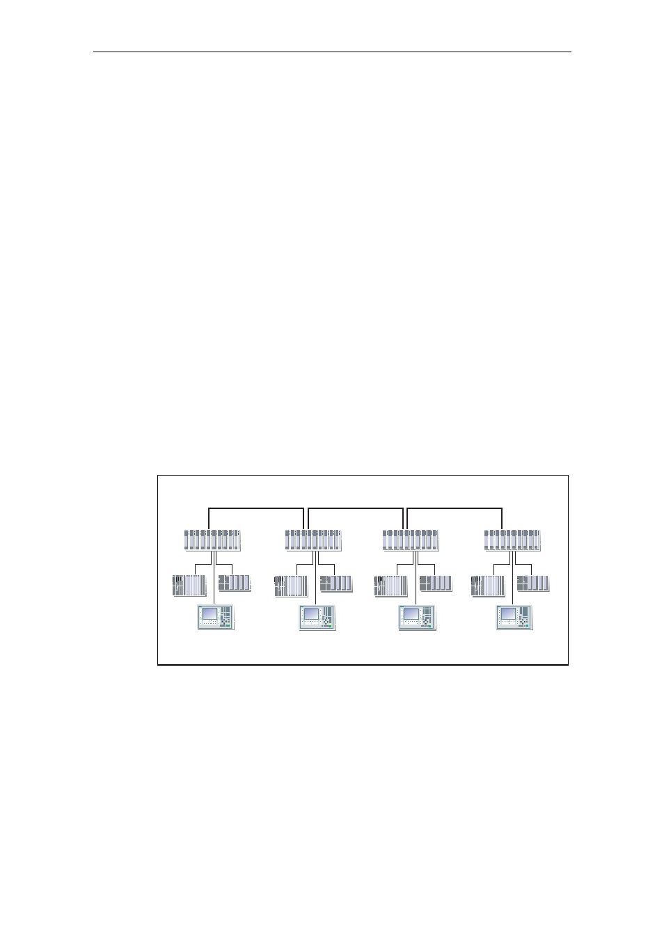
Configuration Example
Sample configuration with SCALANCE X414-3E, SIMATIC S7-300/400 and opera-
tor panel as end devices.
S7-300
S7-400
ET 200S
S7-400
S7-300
S7-300
ET 200S
ET 200S
ET 200S
ET 200S
SCALANCE
X414-3E
S7-300
S7-400
Fiber Optic
SCALANCE
X414-3E
SCALANCE
X414-3E
SCALANCE
X414-3E
Figure 1-5
Line structure (Optical)