Siemens X-400 User Manual
Page 104
Installation and Commissioning
Operating Instructions for SCALANCE X-400 Industrial Ethernet Switches
104
C79000-G8976-C186-03
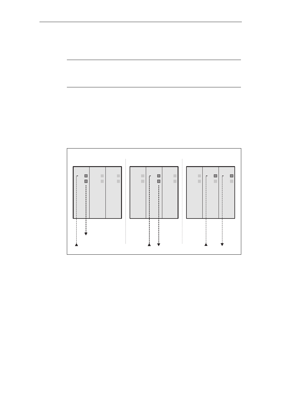
Possible Settings of the Ring Ports
Note
Only two ports of a switch can ever be defined as ring ports. All other ports in slots
6 and 7 that are not defined as ring ports can be used for the optical connection of
nodes or subnets.
● Switch 1:
In the schematic below, switches R1 and R2 are set to OFF.
● Switch 2:
In the schematic below, switch R1 is set to ON and R2 is set to OFF.
● Switch 3:
In the schematic below, switch R1 is set to OFF and R2 is set to ON.
7
6
5
P 1
P 2
P 1
P 2
P 1
P 2
7
6
5
P 1
P 2
P 1
P 2
P 1
P 2
7
6
5
P 1
P 2
P 1
P 2
P 1
P 2
P o r t 1
P o r t 1
P o r t 1
P o r t 1
P o r t 2
P o r t 2
S w i t c h 1
S w i t c h 2
S w i t c h 3
Figure 6-22
The three possible settings for ring ports with R1 and R2