Branch wiring, Cable connection – SMC Networks EtherNet/IP EX500-GEN1 User Manual
Page 9
24VDC
24VDC
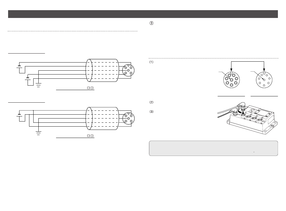
Brown : 0V ( for solenoid valves/output )
White : 24VDC ( for solenoid valves/output )
Gray : Ground ( PE )
Blue : 0V ( for input and controlling GW/SI )
Black : 24VDC ( for input and controlling GW/SI )
Cable Part No. : EX500-AP -
24VDC
Brown : 0V ( for solenoid valves/output )
White : 24VDC ( for solenoid valves/output )
Gray : Ground ( PE )
Blue : 0V ( for input and controlling GW/SI )
Black : 24VDC ( for input and controlling GW/SI )
Cable Part No. : EX500-AP -
Power supply
connector
Power supply
connector
1
3
4
5
2
1
3
4
5
2
14
15
Wiring ( continued )
Separate wiring for power supply for solenoid valves/output and
for input and control of GW/SI
Both single power supply and two power supply systems can be adopted, however, the
wiring shall be made separately ( for solenoid valves/output and for input and controlling
GW/SI ) for either system.
A. Two power supplies
Branch wiring
For wiring with solenoid valves or input devices, connect the branch cable with M12
connector to communication ports A to D.
There are two types of cables different in connector shape ---- straight type and angle
type. As each cable contains power supply wire, there is no need to supply the power to
solenoid valves or input devices individually.
Cable connection
Aligning the key groove with the
connector ( socket ) of GW unit, plug in
the cable ( plug ).
2
3
4
5
6
7
1
8
1
7
6
5
4
3
2
8
Socket Connector Pin Layout
Plug Connector Pin Layout
Tighten the lock nut on cable side by
turning it clockwise by hand.
Confirm that the connector portion does
not move.
NOTE
Mount a waterproof cap on each unused connector of GW unit. The proper use of
waterproof cap can achieve IP65 Enclosure. ( Tightening torque : 0.1N m for M12 )
B. Single power supplies