Ex500 part names, Dimensions ( unit : mm ), Installation ( unit : mm ) – SMC Networks EtherNet/IP EX500-GEN1 User Manual
Page 5: Ex500 body, Thread mounting
6
7
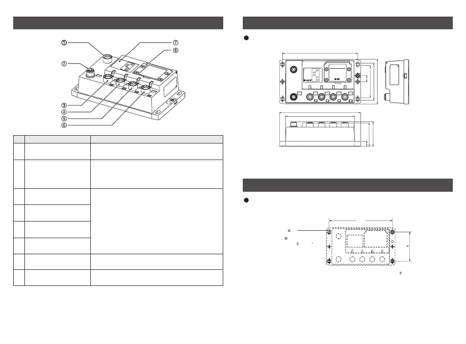
EX500 Part Names
Communication
connector
1
2
3
4
5
6
7
8
Note1 : For wiring method, refer to subsection "Wiring" ( page 11 ) of section "EX500" in this
manual.
Note2 : For display and setting method, refer to subsection "Display/Switch Setting" ( page 18 )
of section "EX500" in this manual.
Power supply connector
Communication port A
( COM A )
Communication port B
( COM B )
Communication port C
( COM C )
Communication port D
( COM D )
Display
Connect with EtherNet/IP line. ( Note 1 )
Name
No.
Application
Supply power for output devices such as solenoid
valve, for input devices such as sensor, and for
controlling GW/SI by using power supply connector
cable. ( Note1 )
Display the power supply status and communication
status with PLC. ( Note2 )
Station number switch
protective cover
Set IP address and communication method by using
the switches under this cover. ( Note2 )
Connect SI unit ( manifold valve ) or Input unit by
using branch cable with M12 connectors. ( Note1 )
Dimensions ( unit : mm )
148
12
63
73
88
10
160
136
46
48.8
EX500 SERIES
GATEWAY UNIT
24VDC
COM A
COM B
COM C
COM D
PE
LAN
NS
MS
100
LINK
PWR
EX500-G
EN1
EX500 body
Cutout Dimensions for Mounting ( Tolerance : 0.2 )
148
68 5
4 M5
Tightening torque :
(1.5 0.2) N m
Installation ( unit : mm )
Thread mounting
Secure at four positions with screws with head diameter of 5.2 or more and thread
length of 15mm or more.