Dimensions ( unit : mm ), Input unit manifold part names – SMC Networks EtherNet/IP EX500-GEN1 User Manual
Page 15
27
26
Dimensions ( unit : mm )
When only input blocks for M8 connector are connected
44.2
39.7
L3
(L4)
5
L1
L2 ( Rail mounting pitch: 12.5 )
DIN Rail
35
49
32.2
(7.5)
When only input blocks of 8-point-integrated type are connected
L1 [mm] : Rail length
L2 [mm] : Mounting pitch
L3 [mm] : Manifold length
L4 [mm]
98
110.5
123
135.5
148
160.5
173
185.5
87.5
100
112.5
125
137.5
150
162.5
175
74
86
98
110
122
134
146
158
12
12
12.5
12.5
13
13
13.5
13.5
Stations
1
2
3
4
5
6
7
8
L1 [mm] : Rail length
L2 [mm] : Mounting pitch
L3 [mm] : Manifold length
L4 [mm]
135.5
185.5
125
175
110
158
12.5
13.5
Stations
1
2
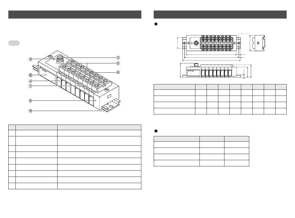
Input Unit Manifold Part Names
The Input unit manifold consists of Input unit, input block (s), end block and DIN rail.
The input block up to 8 can be connected ( 16 points ).
Any combination of input blocks ( for M8 connector, M12 connector and 8-point-
integrated type ) is acceptable.
Input unit
1
Note1 : For wiring method, refer to subsection "Wiring" ( page 30 ) of section "Input Unit
Manifold" in this manual.
Note2 : For display, refer to "Display" ( page 31 ) in section "Input Unit Manifold" in this manual.
Unit to communicate with GW unit or SI unit.
Communication
connector
2
To be connected with branch cables from GW unit or
SI unit ( branch cable with M12 connector ). ( Note1 )
Power LED
3
Indicates the power supply status. ( Note2 )
Input block
4
Unit for sensor signal input.
Sensor connector
5
Connects with sensor. ( Note1 )
Indicator LED
6
Indicates sensor signal status. ( Note2 )
Marker
7
To be used for writing input No. etc.
End block
8
Composes the end of Input unit manifold.
DIN rail
9
To be mounted with Input unit manifold.
Part name
No.
Application
Figure shows the configuration when only input blocks for M8 connector are connected.
Do not mix sensor input specifications ( PNP and NPN ).
Note