Specification, Installation – SMC Networks EtherNet/IP EX500-GEN1 User Manual
Page 16
29
28
Specification
Specifications for Input unit
Connected block
Current source type input block ( PNP input block )
or
Current sink type input block ( NPN input block )
Connected block station
Max. 8 blocks
Supply voltage for block
24VDC
Supply current for block
Current consumption
0.65A Max.
100mA or less ( at rated voltage )
Short circuit protection
Operates at 1A Typ. ( Cuts power supply. )
Can be reset by returning the power after cutting the
power supply to input and control section of GW unit.
Item
Specification
Applicable sensor
Current source type
( PNP output )
Current sink type
( NPN output )
No. of input points
2 points/8 points ( for M8 connector only )
Rated voltage
24VDC
Logical "1" input voltage
15V to 26.4V
0V to 8V
Logical "0" input voltage
0V to 5V
19V to 26.4V
Logical "1" input current
5mA Typ.
-5mA Typ.
Logical "0" input current
1.5mA
Input delay time
1msec. or less
Indicator LED
Green LED
Insulation
Supply current to sensor
N/A
Max. 480mA/Input unit manifold
-1.5mA
Item
Specification
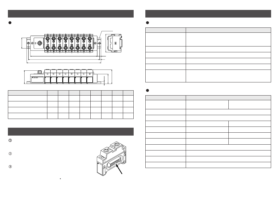
Specifications for input block
When only input blocks for M12 connector are connected
(L4)
5
L3
L1
L2 ( Rail mounting pitch : 12.5 )
60
46.9
DIN Rail
44.2
35
32.2
(7.5)
Connect each connector of Input unit, input blocks,
and end block ( portion indicated by arrow in the
figure to the right ).
Holding with hands so that there will be no gap
between blocks, place the jointed unit and blocks on
DIN rail.
Tighten the bolts of Input unit and end block to
secure the jointed unit and blocks to DIN rail.
Be sure to tighten the bolts by proper tightening
torque. ( Tightening torque : 0.6N m )
Installation
L1 [mm] : Rail length
L2 [mm] : Mounting pitch
L3 [mm] : Manifold length
L4 [mm]
110.5
123
148
173
185.5 210.5
223
248
100
112.5 137.5 162.5
175
200
212.5 237.5
82
102
122
142
162
182
202
222
12
12
12.5
12.5
13
13
13.5
13.5
Stations
1
2
3
4
5
6
7
8
Dimensions ( unit : mm ) (continued )