Display, Wiring, Branch wiring – SMC Networks EtherNet/IP EX500-GEN1 User Manual
Page 17: Sensor wiring
31
30
Correspondence between input number and input block
Input block up to 8 can be connected ( 16 points ).
Input numbers are 0 to 15 from Input unit side.
0
0
1
0
1
0
1
0
1
0
1
0
1
0
1
0
1
2
4
6
8
10
Input unit
12
14
1
3
5
7
9
11
13
15
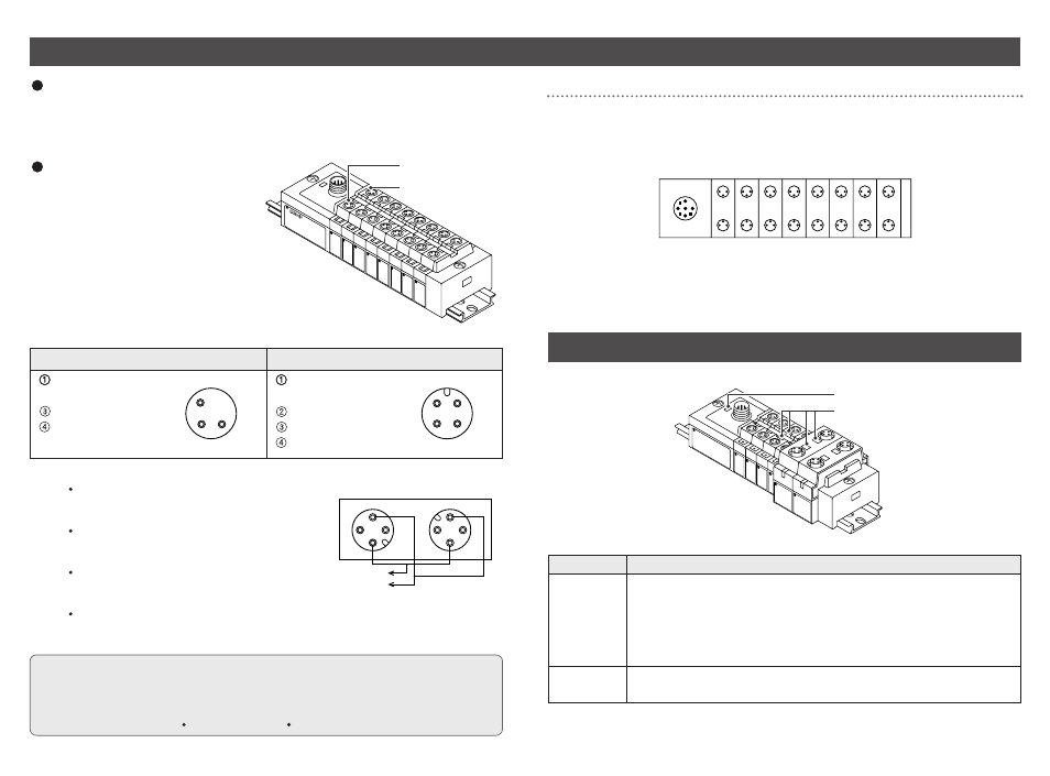
Display
Power LED
Indicator LED
Power LED
Lights on : Power for input and controlling GW is supplied.
Blinks : Under short circuit protection ( abnormal status ).
As the short circuit protective function is operating, the power
is not supplied.
To cancel blinking, turn off and return the power to GW unit.
Lights off : Power for input and controlling GW is not supplied.
Indicator
LED
Lights on : Sensor signal input ON ( logical "1" )
Lights off : Sensor signal input OFF ( logical "0" )
Display
Description
Wiring
Branch wiring
For wiring method, refer to subsection "Wiring" ( page 15 ) of section "EX500" in this
manual. To input devices such as sensor, the power is supplied through the branch
wiring ( branch cable with M12 connector ). Therefore, there is no need to supply the
power to them individually.
Sensor connector "1"
Sensor connector "0"
M12 Block
1
1
3
3
4
2
2
4
key
key
0
1
Input "0" ( n ) side
Input "1" ( n+1 ) side
Input "1" ( n+1 )
Input "0" ( n )
Sensor wiring
Connect sensors to the sensor
connectors of input block.
Pin layout of sensor connector
M8 connector ( 3-pin socket )
M12 connector ( 4-pin socket )
Power supply
( 24VDC )
Power supply ( 0V )
Input
Power supply
( 24VDC )
( Input ) ( Note )
Power supply ( 0V )
Input
1
2
4
3
1
4
3
Note : Internal wiring of M12 input block and key position for mounting sensor connector
No. 2 pins of M12 input block connectors are
wired to each other’s sensor signal input pins
( No. 4 pins ) internally.
This wiring enables direct input of signals from
two points combined into one cable through
concentric connector etc.
When connecting sensors, confirm the
specification of output signal carefully.
Otherwise malfunction can result.
The key position for mounting sensor
connector is as shown to the right. Consider
this key position when selecting sensor.
NOTE
Mount a waterproof cap on each unused connector of Input unit. The proper use of
waterproof cap can achieve IP65 Enclosure. The waterproof caps are delivered
together with each input block as accessories.
( Tightening torque : 0.05N m for M8 and 0.1N m for M12 )