Wiring ( continued ) communication wiring, Power supply wiring, Cable connection – SMC Networks EtherNet/IP EX500-GEN1 User Manual
Page 8
12
13
Wiring ( continued )
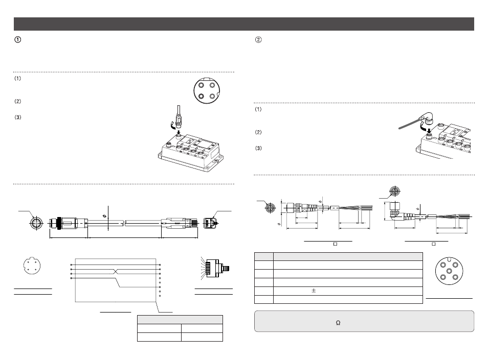
Communication wiring
Aligning the key groove with the communication connector
( 4-pin, socket ) of GW unit, plug the Ethernet
communication cable ( plug ).
Tighten the lock nut on cable side by turning it
clockwise by hand.
Confirm that the connector portion does not move.
Pin layout and connection diagram of cable with Ethernet communication connector
Cable connection
Connect the cable with Ethernet communication connector to the communication
connector of GW unit.
1
2
3
4
4
3
2
1
Connect the communication cable with socket-type M12 connector to the
communication connector of GW unit.
Power supply wiring
Connect the power supply connector cable to the power supply connector of GW unit.
There are two types of cables different in connector shape ---- straight type and angle
type. With this cable, the power is supplied to the output devices such as solenoid valve,
and the input devices such as sensor, and for controlling GW/SI. Therefore, there is no
need to supply the power to other units individually.
When selecting the power supply, refer to "Handling precautions" ( page 3 ) in this manual.
Cable connection
Aligning the key groove with the power supply
connector ( plug ) of GW unit, plug the power supply
cable ( socket ).
Tighten the lock nut on cable side by turning it
clockwise by hand.
Confirm that the connector portion does not move.
Pin layout and connection diagram of power supply connector cable for ( unit : mm )
( Pin layout and connection diagram are common to all cables. )
2
4
3
5
1
Socket Connector Pin Layout
Straight connector Type
Angle connector Type
EX500-AP -S
EX500-AP -A
M12
M12
14.9
48
34
18
6
30
5
50
31.3
28.3
30
5
50
6
Pin No.
5
4
3
2
1
Cable color: Signal name
Brown : 0V ( for solenoid valves/output )
White : 24VDC +10%/-5% ( for solenoid valves/output )
Blue : 0V ( for input and controlling GW/SI )
Black : 24VDC
10% ( power supply for input and controlling GW/SI )
Gray : Ground ( PE )
NOTE
Connect a ground cable of 100
or less to PE terminal.
1
3
4
2
M12
1
2
+Rx
3
- Tx
4
- Rx
1
2
3
4
5
6
7
8
Shield
RJ45
6.7
47.3
45
2000
EX9-AC020EN-PSRJ
+Tx
Wiring diagram
Cable core wire external color
Terminal No.
Pin assignment of
plug connector
Pin assignment of
plug connector
White/Orange
Orange
White/Green
Green
8
7
6
5
4
3
2
1
Core wire color
Sheath color
Cable specifications
AWG 26
Blue green