Wiring, Mounting, Output wiring – SMC Networks EtherNet/IP EX500-GEN1 User Manual
Page 19
35
34
Wiring
Output wiring
Connect output devices to the output connectors.
EX9-OET1/EX9-OET2/
EX9-OEP1/EX9-OEP2 output connectors
M12, 5-pin, socket
NOTE
Mount a waterproof cap to each unused connector. The proper use of waterproof cap
can achieve IP65 Enclosure. ( Tightening torque for M12 : 0.1N m )
2
4
3
5
1
1
Output connector
No.0
Output connector
No.1
Output connector
No.0
Output connector
No.1
Model No.
Pin No.
EX9-OET2/EX9-OEP2
EX9-OET1/EX9-OEP1
NPN output
Power supply
( 24VDC )
Power supply
( 24VDC )
NC
NC
2
Output ( OUT1 )
NC
Output ( OUT 1 )
NC
3
NC
NC
Power supply
( GND )
Power supply
( GND )
4
Output ( OUT 0 )
Output ( OUT 1 )
Output ( OUT 0 )
Output ( OUT 1 )
5
NC
NC
NC
NC
PNP output
NC : Not connected
Two outputs are available with only output connector No. 0.
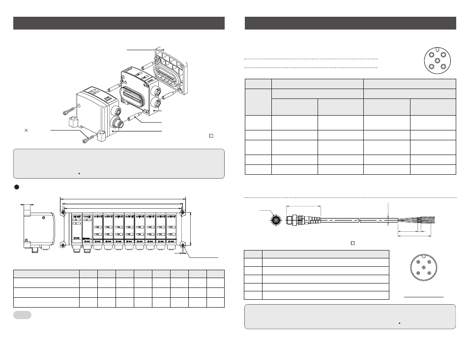
Mounting
M3 18 : 2 pcs.
( Hexagon socket head
cap screw ( with spring washer ))
Supply/exhaust block assembly,
end plate R, power block, or other
EX9 series general purpose output block
Power block or EX9 series
general purpose output block
Tie-rod : 4 pcs.
SI unit for general purpose
output block ( EX500-Q 02 )
L dimensions
The mounting and removing methods of each SI unit are as shown below.
NOTE
Holding with hand so that there will be no gap between units and tighten the bolts.
Be sure to tighten each bolt by specified tightening torque.
( Tightening torque : 0.6N m )
Dimensions when general purpose output block is connected
0
1
13
0
1
0
1
0
1
0
1
0
1
0
1
0
1
PWR
PWR
COM
EX500
series
L2
L3
L1
Mounting hole for:
M4 places
66
1.5
PWR
L1 [mm]
83
104
125
146
167
188
209
230
L2 [mm]
72
93
114
135
156
177
198
219
L3 [mm]
67
88
109
130
151
172
193
214
No. of output block stations
1
2
3
4
5
6
7
8
The above dimensions show those when one unit of power block ( width : 21mm ) is
combined. For details, refer to the instruction manuals, technical data, etc. of EX9
series general purpose output block.
Note
Pin alignment and connection drawing of the Output Cable
Plug connector pin layout
EX9-AC
-7
M12
6.4
30
5
50
52
Pin No.
5
4
3
2
1
Cable color : Signal name
Brown : NC
White : Output No.1/NC
Blue : GND
Black : Output No.0/Output No.1
Gray : NC