Serial interface, Input connector, Pin configuration – Seiko FB-900 User Manual
Page 170: Timing chart
●
Serial interface
7-5
— 7. Interface specifications —
Serial interface
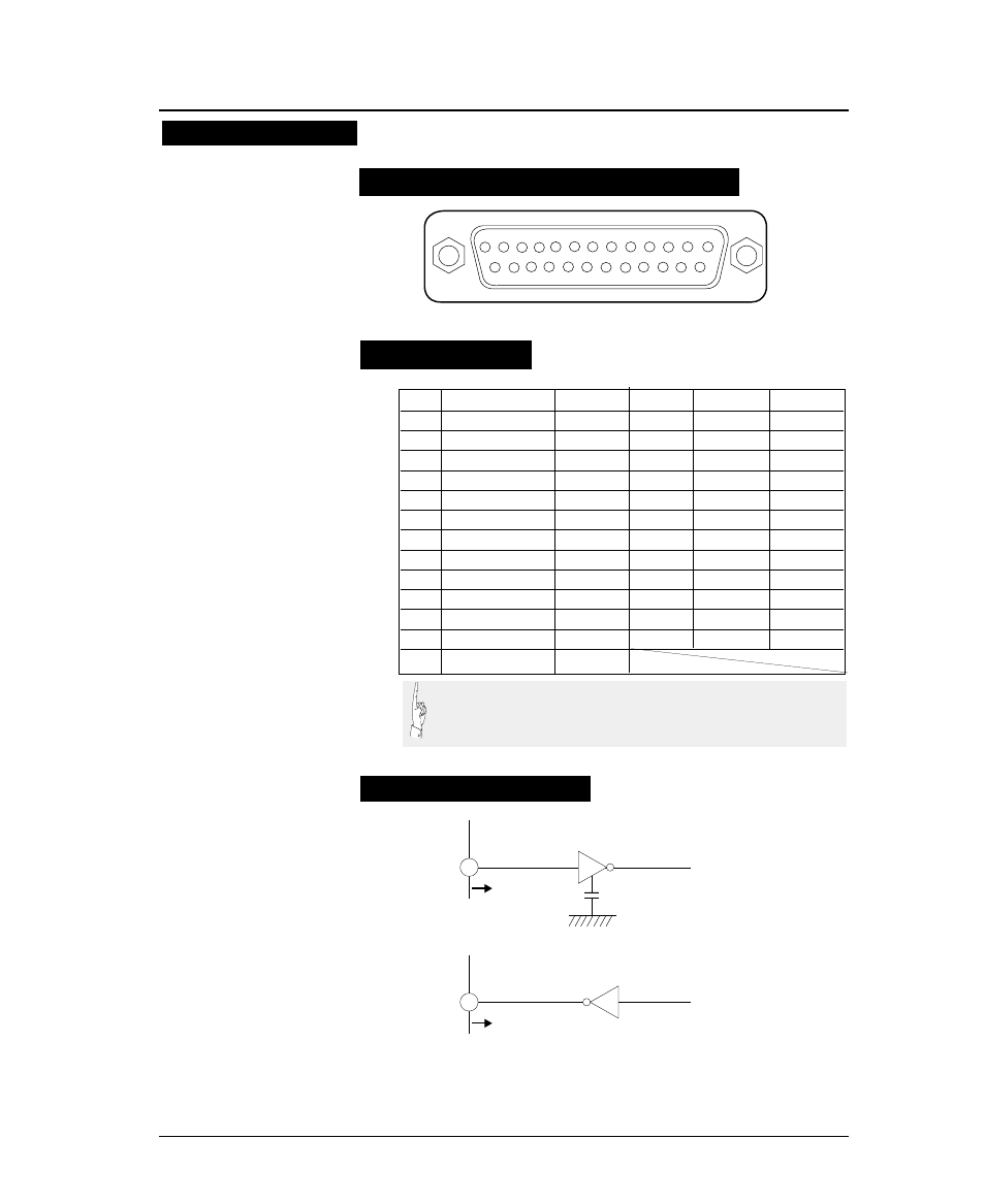
Pin configuration
Input connector (25-pin serial connector)
1
3
2
4
5
6
7
8
9
10
11
12
13
15 14
16
17
18
19
20
21
22
23
24
25
PIN
SIGNAL
IN/OUT
PIN
SIGNAL
IN/OUT
1
CHASSIS GND
14
NC
2
TXD
OUT
15
NC
3
RXD
IN
16
NC
4
RTS
OUT
17
NC
5
CTS
IN
18
NC
6
DSR
IN
19
NC
7
SIGNAL GND
20
DTR
OUT
8
CD
IN
21
NC
9
NC
22
NC
10
NC
23
NC
11
SRTS
OUT
24
NC
12
NC
25
NC
13
NC
To printer
INPUT
330pF
(75189 or equivalent)
To printer
OUTPUT
(75188 or equivalent)
Signal levels
OFF: Indicates "MARK" at a level from -3 to -15 V.
ON: Indicates "SPACE" at a level from +3 to +15 V.
Input signal
Output signal
Input/output conditions
(1) NC means "not connected".
(2) The CHASSIS GND and SIGNAL GND are connected inside
the printer.