Rear terminal, Part names and functions – Sanyo PLC WM5500L User Manual
Page 11
11
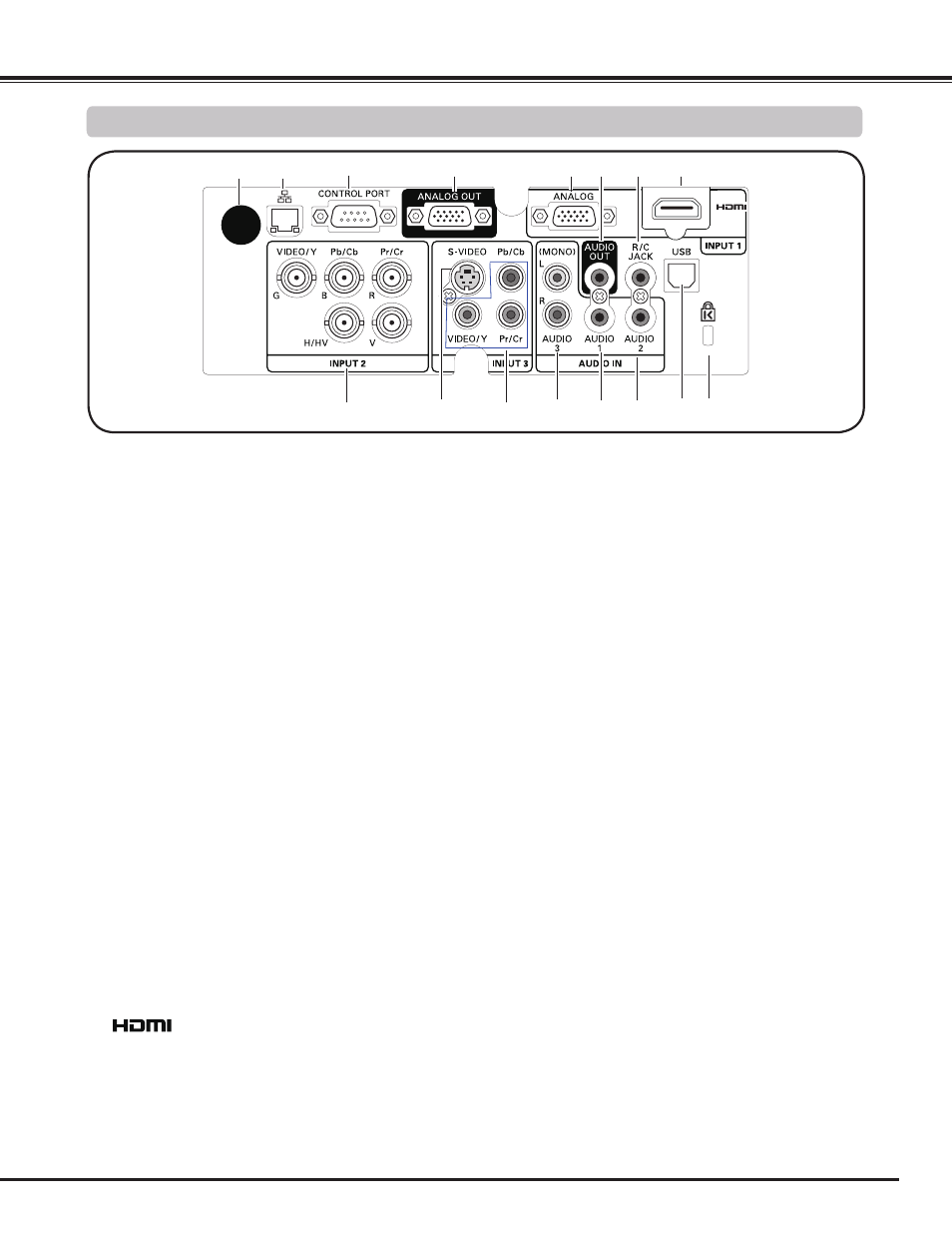
⑦ R/C jACK
When using the wired remote control, connect the wired remote
control to this jack with a remote control cable (not supplied)
(p.15).
⑮ USB CONNECTOR (Series B)
Use this connector when controlling a computer
with the remote control of the projector. Connect
the USB terminal of your computer to this
connector with a USB cable (p.19).
⑭ AUDIO jACK
Connect the audio output (stereo) signal from a
computer or video equipment (p.21).
⑪ VIDEO INPUT jACK
Connect the component or the composite video
output signal from video equipment to these
jacks (p.20).
③ CONTROL PORT CONNECTOR
When controlling the projector with RS-232C, connect the
control equipment to this connector with the serial control cable.
(p.19)
⑧ HDMI TERMINAL
Connect the HDMI signal (including sound signal) from video
equipment or the DVI signal from computer to this terminal (pp.19,
20).
is registered trademarks of HDMI
Licensing, LLC.
⑤ COMPUTER INPUT TERMINAL (ANALOG)
Connect the computer (or RGB scart) output signal to this
terminal (pp.19-20).
⑨ 5 BNC INPUT jACKS
Connect the component or composite video
output signal from video equipment to VIDEO/
Y, Pb/Cb, and Pr/Cr jacks or connect the
computer output signal (5 BNC Type [Green,
Blue, Red, Horiz. Sync, and Vert. Sync.]) to G,
B, R, H/V, and V jacks (pp.19-20).
③
Part Names and Functions
⑩ S-VIDEO INPUT jACK
Connect the S-VIDEO output signal from video
equipment to this jack (p.20).
⑬ AUDIO 1 jACK
Connect the audio output (stereo) signal from a
computer or video equipment (p.21).
④
⑤
⑧
⑪
⑬
⑥ AUDIO OUTPUT jACK (VARIABLE)
This jack outputs the audio signal from computer or video or
HDMI equipment to external audio equipment (p.21).
Kensington Security Slot
This slot is for a Kensington lock used to deter
theft of the projector.
*Kensington is a registered trademark of ACCO Brands
Corporation.
① INFRARED REMOTE RECEIVER (Back)
The infrared remote receiver is also located in the front and top
(pp.10, 15).
④ ANALOG OUT TERMINAL
This terminal can be used to output the incoming analog RGB
signal from INPUT 1-3 terminal to the other monitor (pp.19-20).
⑥
⑦
⑭
⑫
⑨
②
⑮
② LAN CONNECTION TERMINAL
Connect the LAN cable (refer to the owner’s manual of “Network
Set-up and Operation”).
①
⑩
⑫ AUDIO jACKS (L(MONO)/R)
Connect the audio output signal from video
equipment connected to
⑩ or ⑪ to this jack.
For a monaural audio signal (a single audio
jack), connect it to the L (MONO) jack (p.21).
Rear Terminal