Rear panel of an ex4200 switch, Figure 6: ex4200-24f switch with 24 sfp ports – Juniper Networks EX4200 User Manual
Page 37
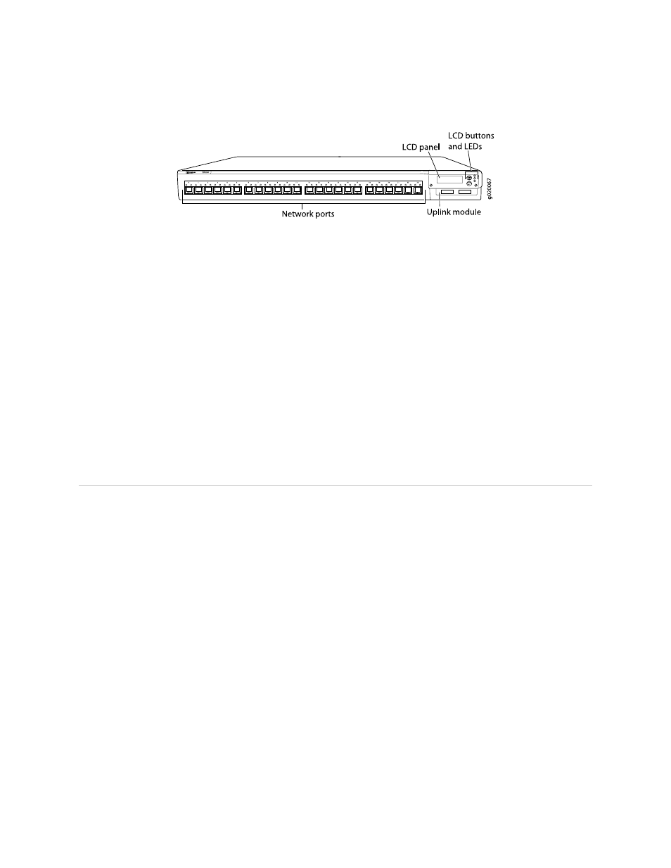
Figure 6: EX4200-24F Switch with 24 SFP Ports
Related Topics
■
Chassis Status LEDs in EX4200 Switches on page 18
■
Rear Panel of an EX4200 Switch on page 11
■
Network Port LEDs in EX3200 and EX4200 Switches on page 20
■
Network Port Connector Pinout Information for an EX3200 or EX4200 Switch
on page 40
■
LCD Panel in EX3200 and EX4200 Switches on page 13
■
Optical Interface Support in EX3200 and EX4200 Switches on page 43
■
Installing and Removing EX3200 and EX4200 Switch Hardware Components on
page 129
■
Installing an Uplink Module in an EX3200 or EX4200 Switch on page 133
■
Removing an Uplink Module from an EX3200 or EX4200 Switch on page 175
Rear Panel of an EX4200 Switch
The rear panel of the EX4200 switch consists of the following components:
■
Fan tray
■
Virtual Chassis ports (VCPs)
■
USB port
■
Temperature shutdown LED
■
Management Ethernet port
■
Console port
■
ESD point
■
Power supply or power supplies
Figure 7 on page 12 shows the rear panel of an EX4200 switch. All EX4200 switches
have the same rear panel. The 320 W AC power supply and the 190 W DC are flush
with the chassis. The 600 W AC power supply and 930 W AC power supply extend
out of the chassis by 2.25 in. Power cord retainer clips extend out of the power supply
by 3 in.
Rear Panel of an EX4200 Switch
■
11
Chapter 1: EX3200 and EX4200 Switches Overview