Figure 7: ex4200 switch rear panel – Juniper Networks EX4200 User Manual
Page 38
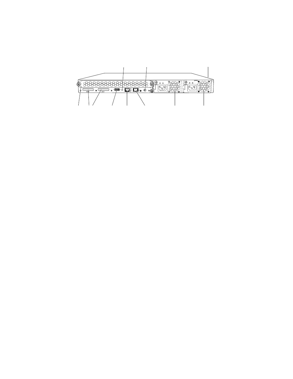
Figure 7: EX4200 Switch Rear Panel
g020084
Virtual
chassis
ports
USB
port
Management
Ethernet
port
Fan
tray
Console
port
Power
Supply 1
Power
Supply 0
Protective earthing
terminal (on side panel)
ESD
point
Temperature
shutdown LED
Related Topics
■
Field-Replaceable Units in EX3200 and EX4200 Switches on page 16
■
Front Panel of an EX4200 Switch on page 10
■
USB Port Specifications for an EX Series Switch on page 39
■
Cooling System and Airflow in an EX4200 Switch on page 32
■
Power Supply in EX3200 and EX4200 Switches on page 26
■
Prevention of Electrostatic Discharge Damage on EX Series Switches on page 236
■
Connecting Earth Ground to an EX Series Switch on page 141
■
Installing and Removing EX3200 and EX4200 Switch Hardware Components on
page 129
■
Understanding Virtual Chassis Hardware Configuration on an EX4200 Switch on
page 101
12
■
Rear Panel of an EX4200 Switch
Complete Hardware Guide for EX3200 and EX4200 Ethernet Switches