Juniper Networks EX4200 User Manual
Page 157
NOTE: The handle on the 320 W AC power supply is at the bottom of the power
supply faceplate, while the handle on the 600 W and the 930 W AC power supplies
is at the top of the faceplate. The handle on the 190 W DC power supply runs across
the faceplate.
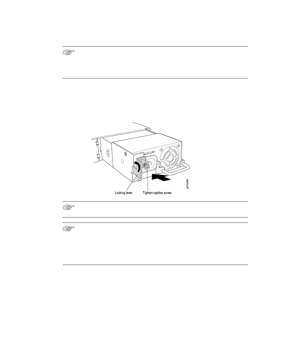
6.
Push the locking lever up to its highest position (this action might pull the power
supply in).
7.
Tighten the locking lever screw by using the Phillips (+) screwdriver, number 2.
Figure 46: Installing a Power Supply in an EX3200 or EX4200 Switch
NOTE: Each power supply must be connected to a dedicated power source outlet.
NOTE: If you have a Juniper J-Care service contract, register any addition, change,
or upgrade of hardware components at
can result in significant delays if you need replacement parts. This note applies if
you change the type of power supply or add a new type of uplink module. It does
not apply if you replace these components with the same type of component.
Related Topics
■
Removing a Power Supply from an EX3200 or EX4200 Switch on page 172
■
Installing and Removing EX3200 and EX4200 Switch Hardware Components on
page 129
■
Power Supply in EX3200 and EX4200 Switches on page 26
■
Field-Replaceable Units in EX3200 and EX4200 Switches on page 16
■
AC Power Cord Specifications for EX3200 and EX4200 Switches on page 98
Installing a Power Supply in an EX3200 or EX4200 Switch
■
131
Chapter 10: Installing Switch Components