Cooling system and airflow in an ex4200 switch, Figure 22: fan tray used in an ex4200 switch – Juniper Networks EX4200 User Manual
Page 58
rear panel is lit. You can see the status of fans and the temperature from the
Show
Environment Status
option in the Status menu in the LCD panel.
Related Topics
■
Field-Replaceable Units in EX3200 and EX4200 Switches on page 16
■
Rear Panel of an EX3200 Switch on page 9
■
Prevention of Electrostatic Discharge Damage on EX Series Switches on page 236
■
Installing a Fan Tray in an EX3200 or EX4200 Switch on page 132
■
Removing a Fan Tray from an EX3200 or EX4200 Switch on page 174
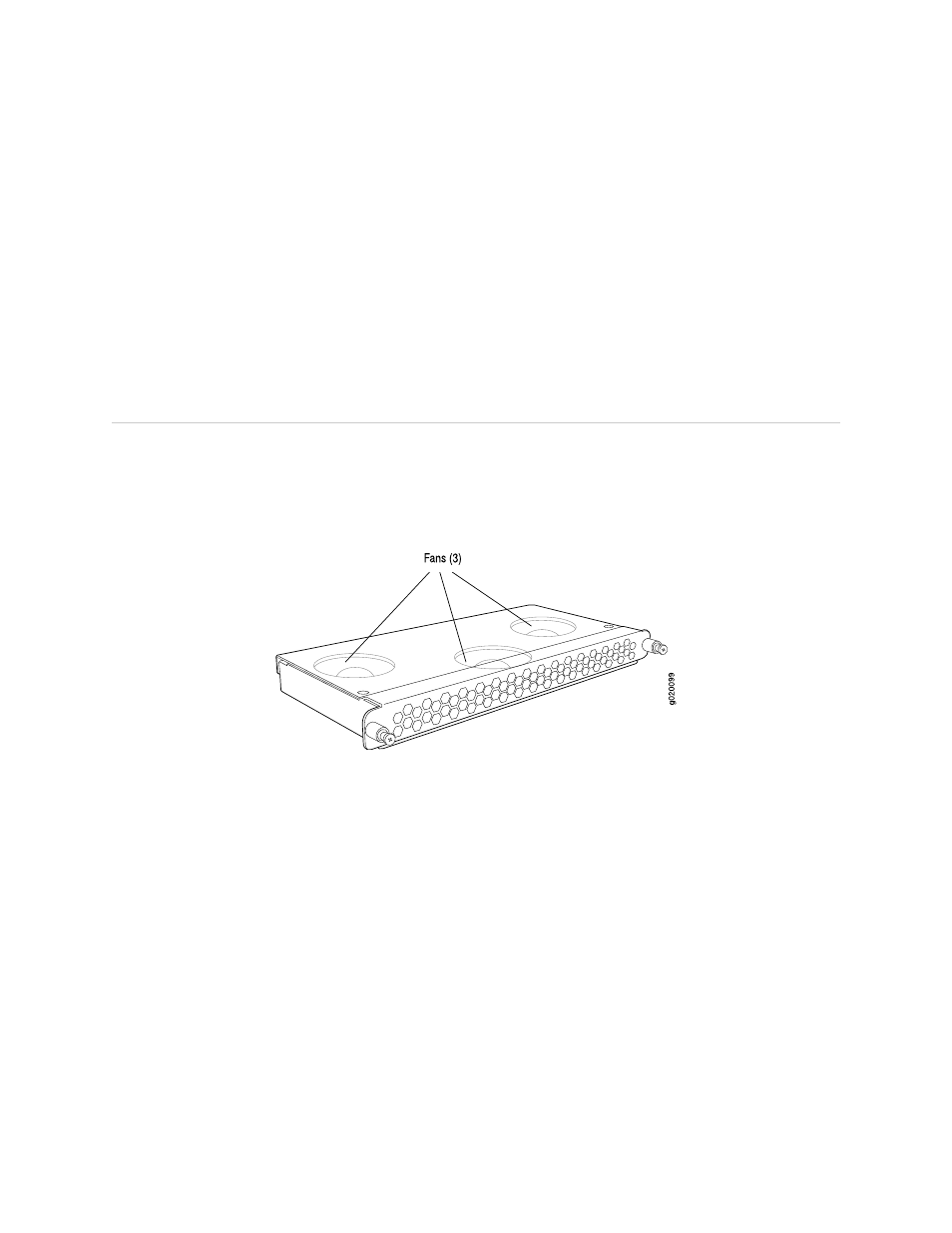
Cooling System and Airflow in an EX4200 Switch
The cooling system in an EX4200 switch consists of a field-replaceable unit (FRU)
fan tray with three fans (see Figure 22 on page 32). The fan tray is located at the
rear of the chassis and provides side-to-rear chassis cooling (see Figure 23 on page 33).
Figure 22: Fan Tray Used in an EX4200 Switch
32
■
Cooling System and Airflow in an EX4200 Switch
Complete Hardware Guide for EX3200 and EX4200 Ethernet Switches