Create linear drain design – John Deere SURFACE WATER PRO OMPFP11362 User Manual
Page 40
Ditch
JS56696,00009E7 1916MAY111/1
Create Linear Drain Design
Surface Water Pro Plus
Select MENU softkey >> GREENSTAR 3 PRO softkey
>> SURFACE WATER PRO softkey >> DITCH tab >>
PROFILE VIEW button >> EDIT DRAIN button.
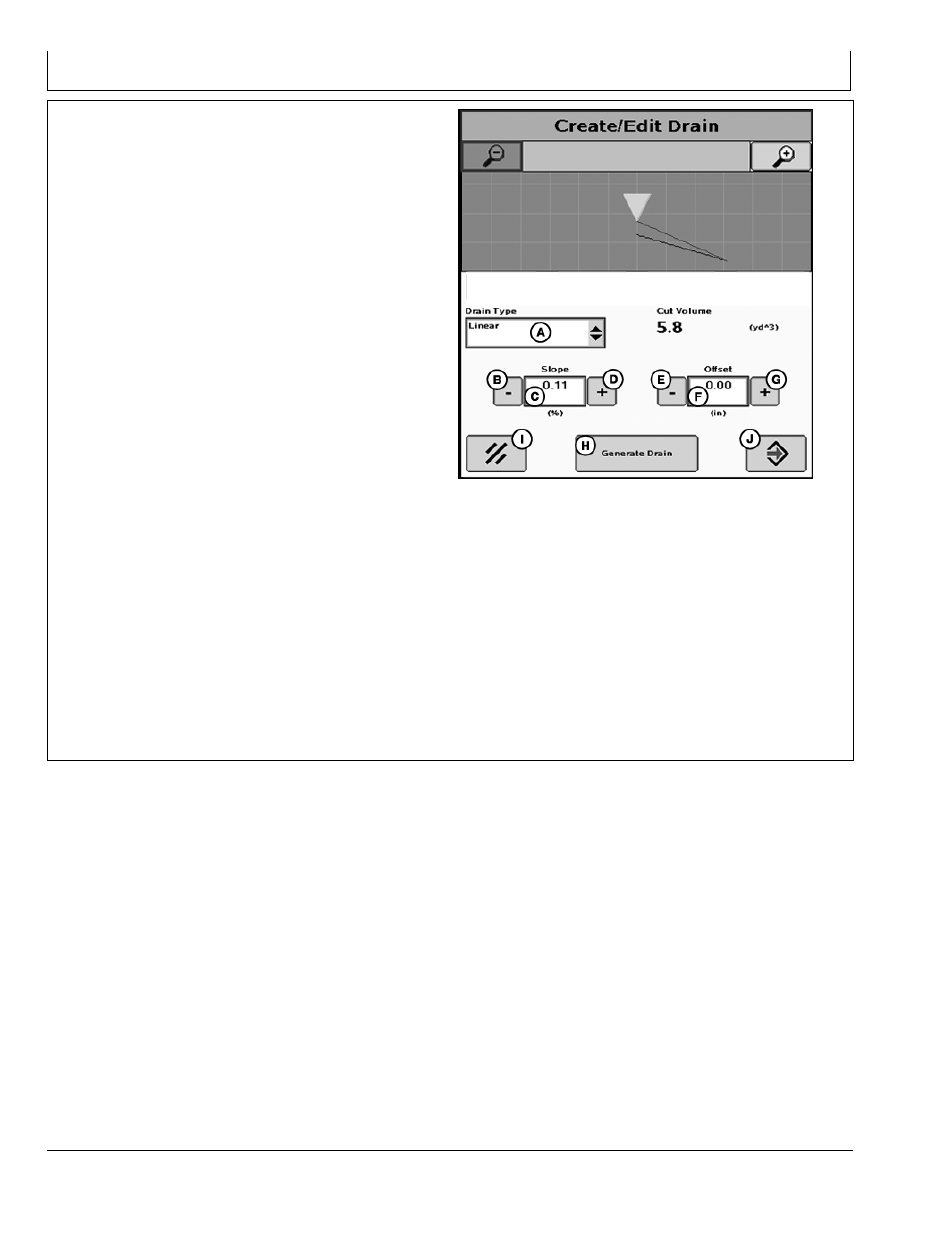
The CREATE/EDIT DRAIN screen provides the ability for
an operator to create or edit a drain design associated
with a ditch track.
The map shows the portion of the survey elevation that
is highlighted on the FullView Map.
The Edit and FullView Map is updated to reflect the new
design of the Linear Drain.
NOTE: The drain design generated is a black line.
Cut Volume is calculated based on Implement
Width. Check before designing drains.
1. Select Drain Type (A)—Linear.
2. Select GENERATE DRAIN button (H). A black line is
displayed. Zoom out to see the entire drain or select
Accept to return to profile view.
3. Adjust the slope of the linear design by using the Slope
or + buttons (B, D) or by selecting the slope input box
(C) and entering the desired slope. Each increase or
decrease adjusts the up or down by + or 0.01%.
4. Select GENERATE DRAIN button (H) again, if
necessary, or adjust offset.
5. Adjust offset up or down by selecting the Offset or +
buttons (E, G) or by selecting the offset input box (F)
and entering the desired offset.
6. Select GENERATE DRAIN (H) again to view updated
design (black line).
PC13732
—UN—17MA
Y1
1
Create or Edit Drain
A—Drain Type dropdown
menu
B—Slope Decrease button
C—Slope input box
D—Slope Increase button
E—Offset Decrease button
F— Offset input box
G—Offset Increase button
H—Generate Drain button
I— Cancel button
J— Accept button
7. Cut volume is updated after each time GENERATE
DRAIN button is selected.
408
061611
PN=40