Figure 27), Figure 27, Figure 28 – Juniper Networks ERX Hardware 8 User Manual
Page 83: Erx-310 router (ac model)
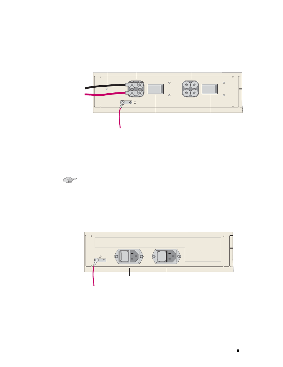
Cabling ERX Routers
Figure 27: ERX-310 Router, Rear View (DC Model)
Ground
Power B
switch
DC power
input B
DC power
input A
Power A
leads
POWER B
POWER
A
-48VDC
RTN
ON
|
O
OFF
-48VDC
RTN
ON
|
O
OFF
Power A
switch
g013753
ERX-310 Router (AC Model)
1.
Insert the power cord into the AC power IEC receptacle. (See Figure 28.)
2.
Insert the other end of the power cord into an appropriate AC power source.
NOTE: To provide redundancy, do not terminate Power A and Power B leads at the
same power source.
3.
Repeat Steps 1–2 for the other power input module, if needed.
Figure 28: ERX-310 Router, Rear View (AC model)
Ground
AC power input A
with switch
AC power input B
with switch
POWER A
POWER B
100-240V ~ 5A
50/60 Hz
|
O
|
O
g013754
Cabling the Router for Power
65